- 12/21/2020
- 14 Min Read
- By: Christian Schaefer
How To Replace The PCV On A B8 Audi S4 (Audi A7, S5, & SQ5)

Audi neatly packaged a lot of important components on the S4's engine beneath the supercharger. While they created a good looking engine, the packaging makes service work tricky. One of the components located under the supercharger is the PCV/air oil separator. The PCV/AOS will affect a vast amount of components in the engine if it should fail and should be changed once it is determined to be the issue.
Along with the PCV/AOS replacement, there are other things you can do while the supercharger is off to save yourself time and headache in the future. These engines use direct-fuel-injection and get carbon-clogged intake valves as a result. Take a look at our DIY blog to see how you can clean those valves.
Audi models and years applicable:
|
|
|
|
Symptoms of a failing Audi PCV:
- Vacuum Leaks
- Illuminated Check Engine Light
- Illuminated Oil Pressure Light
- Rough Idle
- High Oil Consumption
- Lean & Misfire Codes
- Idle Regulation Codes
- Whistling Noise from Engine Cover
- Oil Leak From Rear Main Seal
The Audi 3.0t engines use a crankcase ventilation system, commonly referred to as the PCV, or air/oil separator. If this fails, you can experience numerous symptoms, although some symptoms are more difficult to diagnose than others. PCV related issues can show up at any time, though most begin to appear between 60,000-80,000 miles.
While under load, pressure builds up in the oil pan and crankcase, where there shouldn't be any pressure. The PCV's job is to open up and allow the engine to pull this pressure up through the manifold and into the combustion chamber. However, when the PCV/AOS fails, excess pressure builds in the engine, causing the symptoms listed above.
How long will it take to replace the PCV on a B8 Audi S4?
This job won't be quick. Set aside a full day to complete the job. Removing the supercharger and intake manifolds is a challenge without practice. On top of that, both the coolant and fuel systems need to be opened, and the valves need to be closed completely.
At several points during this DIY, the engine's intake ports will be exposed. Use rags to block the ports and prevent any foreign debris from entering the engine.
How much will it cost to replace the PCV on a B8 Audi S4?
The total parts cost for the job will be around $220. The new PCV/AOS is the majority of that cost, while the gaskets hose and coolant total around $50. On top of that, we recommend that you purchase the $45 034 Motorsports steel supercharger bleeder screws. The plastic factory pieces commonly break. In total, budget around $270 to complete the job yourself. The larger budget gives wiggle room to buy extra rags and brake clean.
Tools required to replace the PCV on a B8 Audi S4:
- 8mm Socket
- 10mm Socket
- 13mm Socket
- 16mm Socket
- 17mm Socket
- 19mm Socket
- 27mm Socket
- T20
- T25
- T30
- 5mm Hex Bit
- Ratchets
- Picks
- Screwdrivers
- Torque Wrench
- Wire Cutters
Parts required to replace the PCV on a B8 Audi S4:
- Audi Crankcase Vent Valve
- Audi Air Oil Separator (B8 S4 ONLY)
- Audi PCV Hose
- Audi Intake Manifold Gasket x6
- Audi Coolant
- Supercharger Bleeder Screw Kit (Optional/Recommended)
Steps required to replace the PCV on a B8 Audi S4:
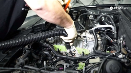
Step 1: Remove the supercharger
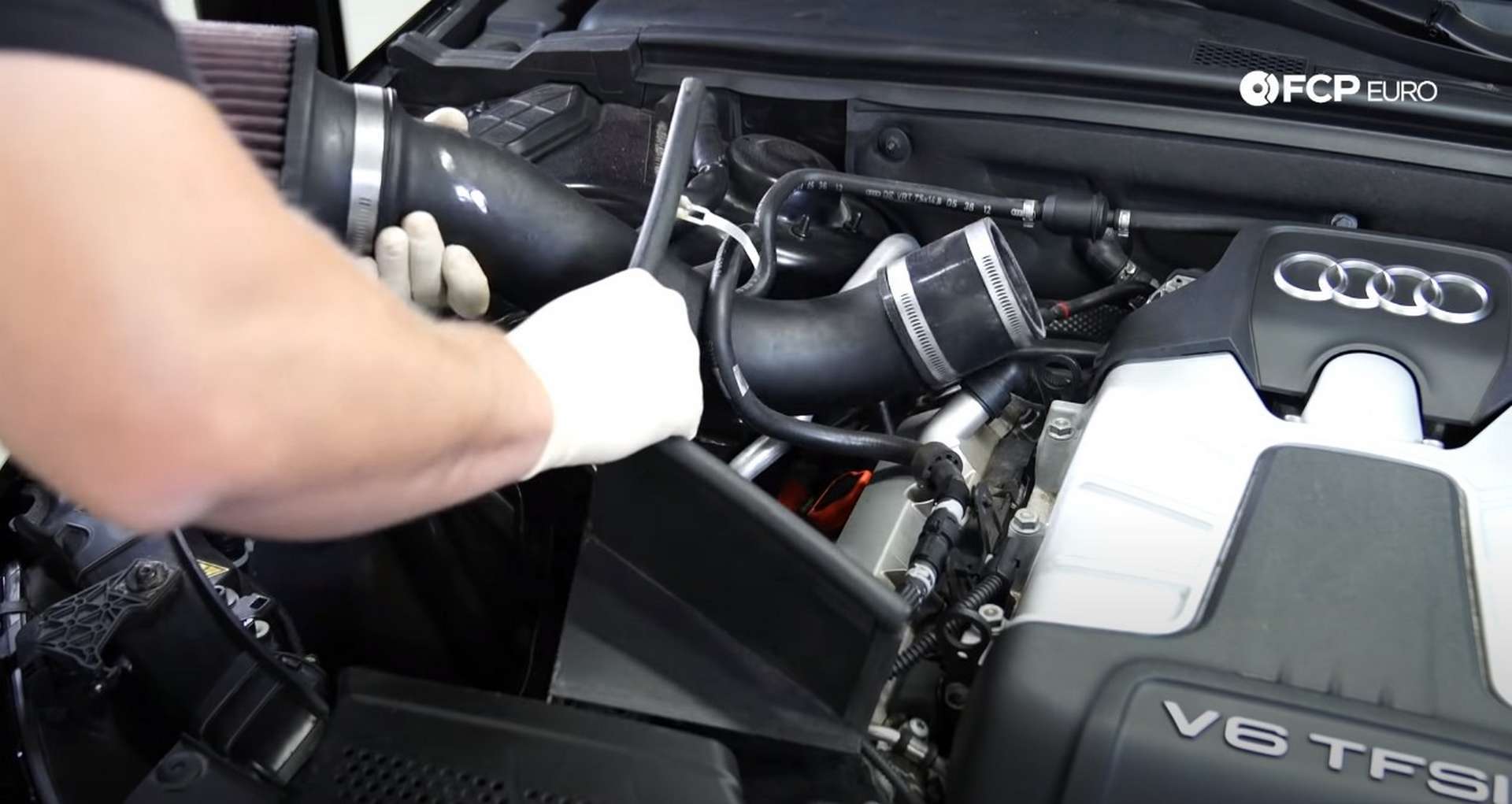
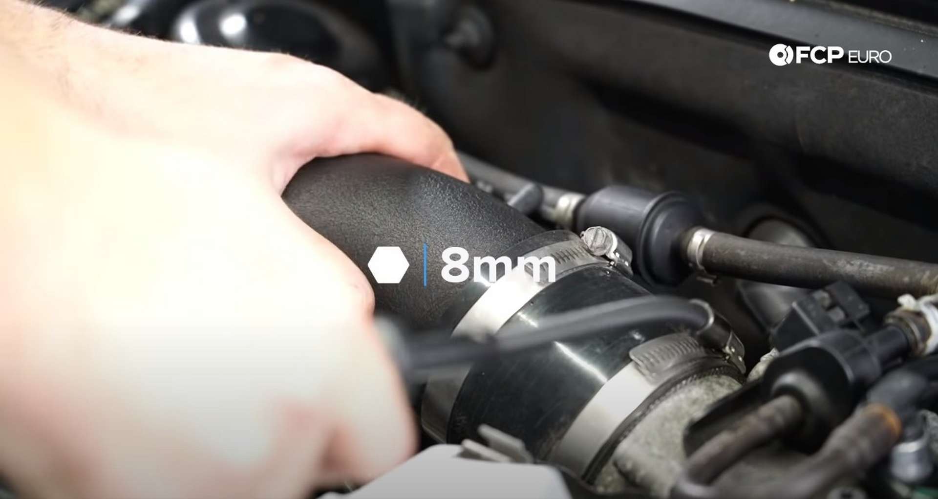
Start by removing any vacuum line from the intake tube. Use an 8mm socket to release the hose clamp for the intake tube on the throttle body and pull up on the airbox to remove it from its mounting grommets. Then, remove the intake assembly from the engine bay.
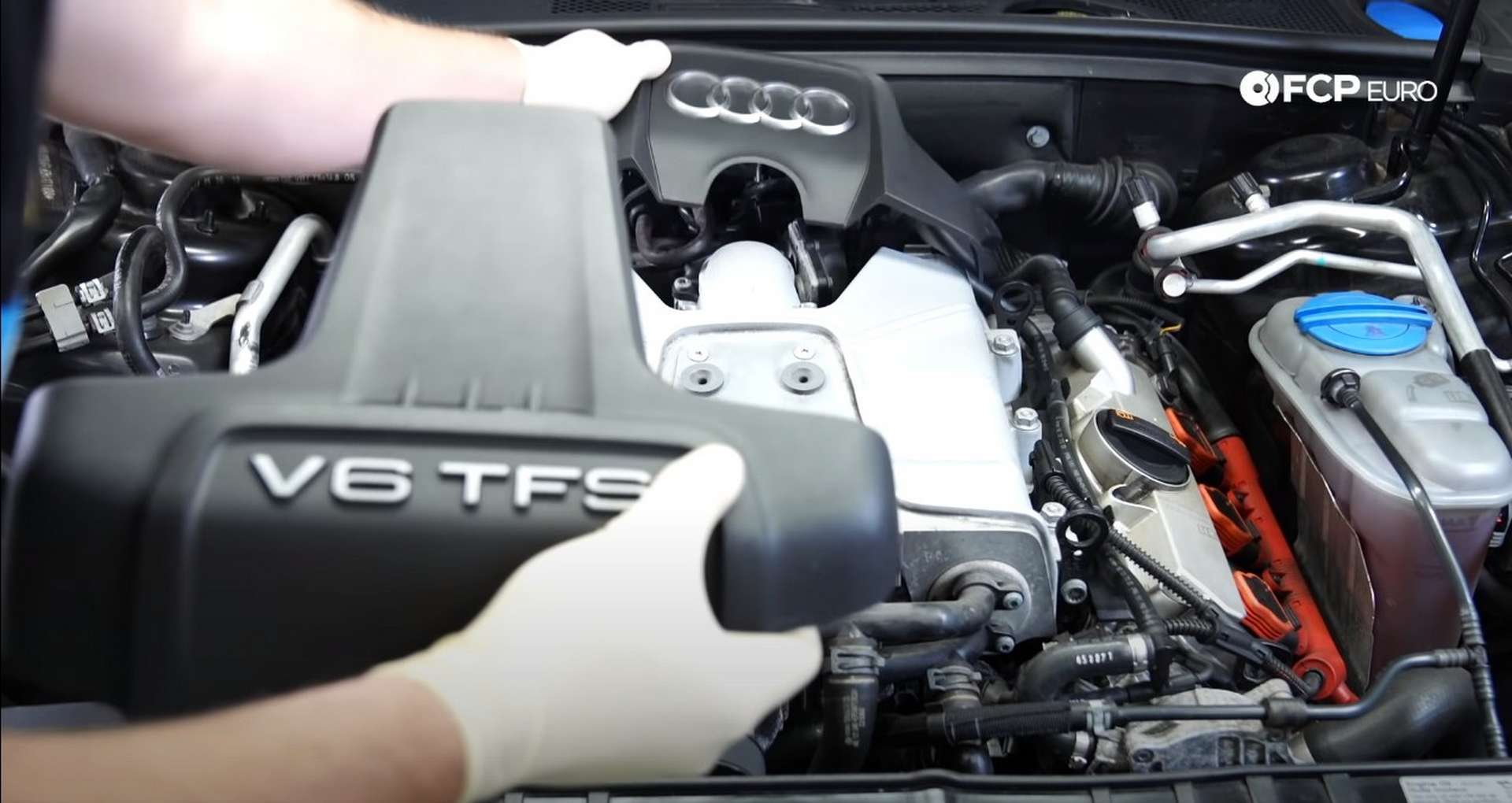
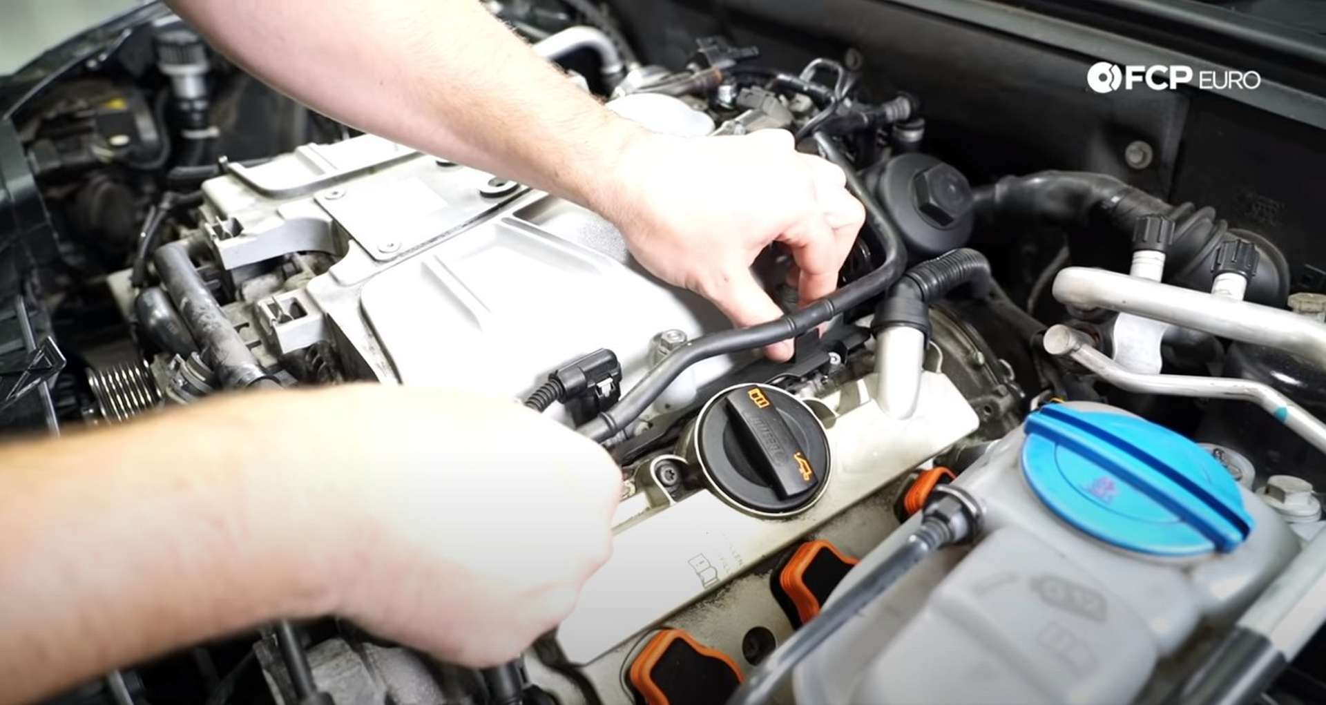
Next, remove the engine dress-up covers to reveal the sensors and solenoids behind the supercharger.
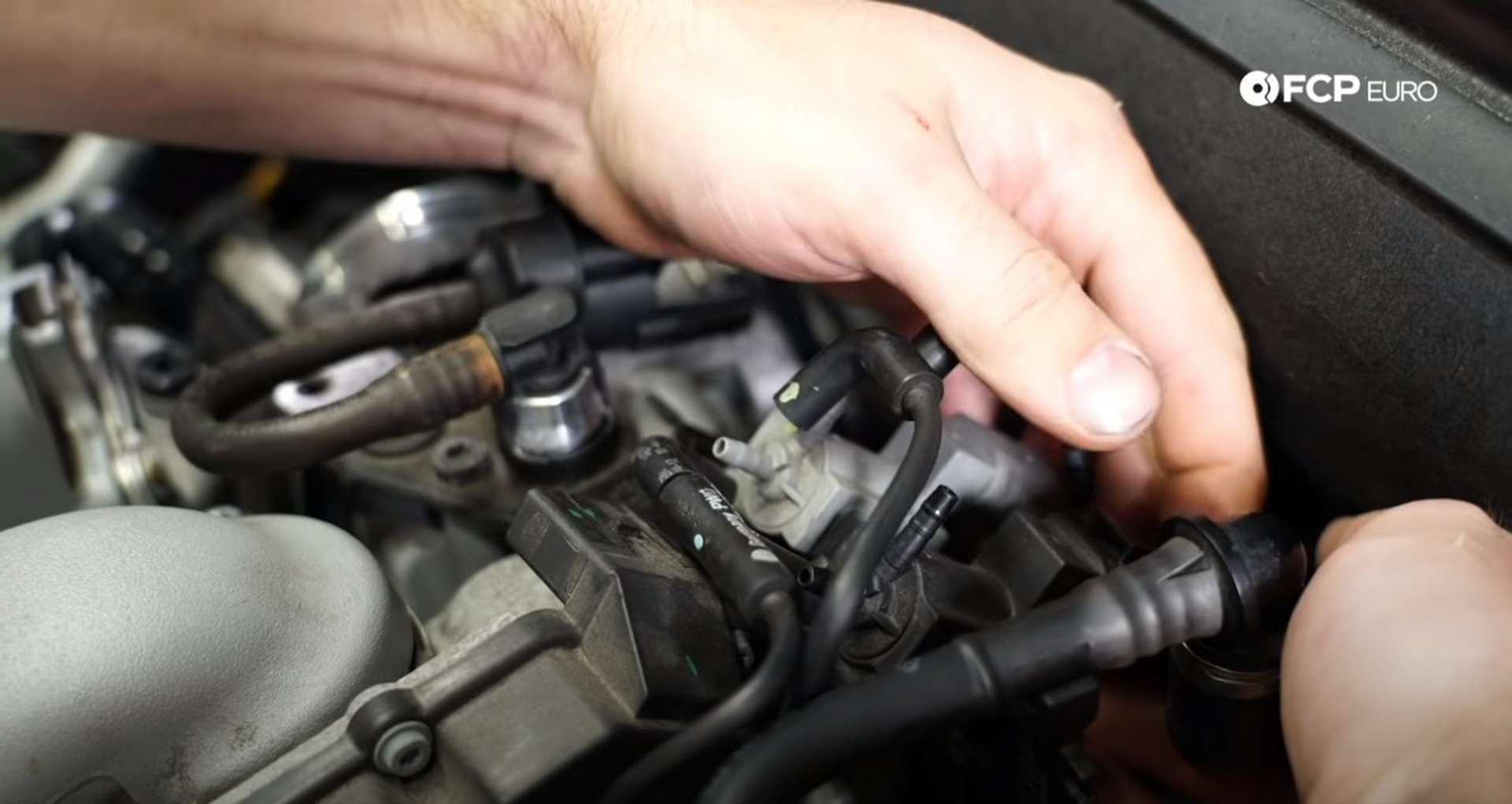
The vacuum lines on the back of the supercharger all have their specific places. Use something like a sharpie to mark the lines to ensure that they don't get mixed up during reinstallation. Then, disconnect all of the electrical connections from the back of the supercharger.
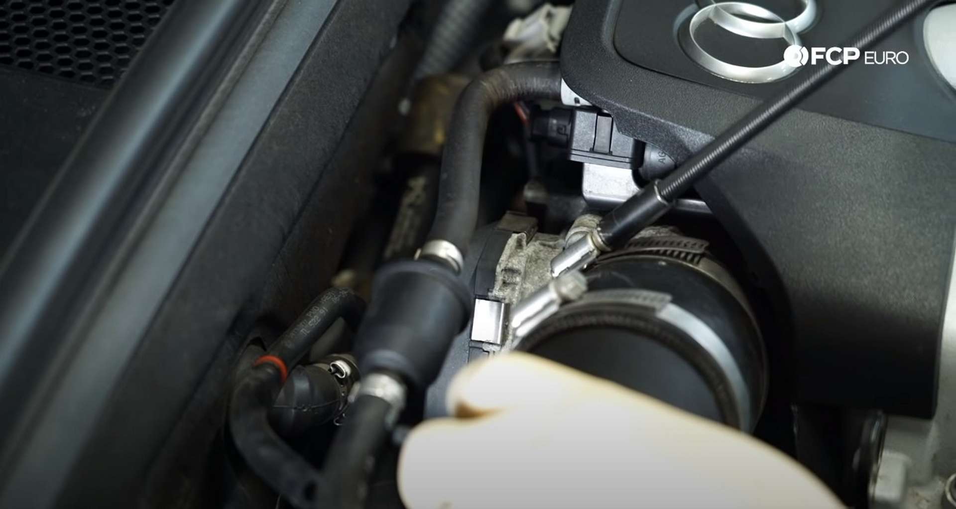
Next, remove the evap hose from the throttle body.
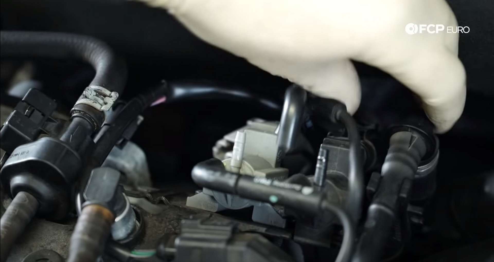
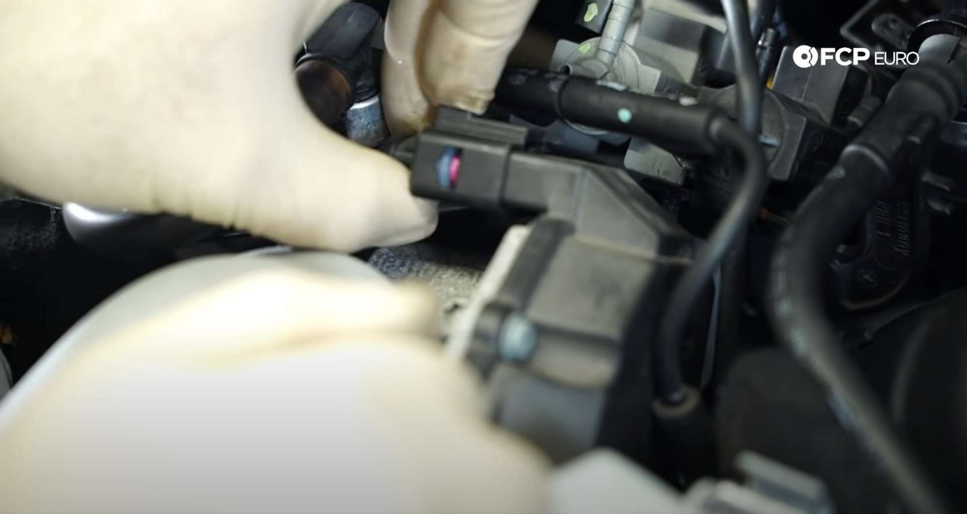
On either side of the supercharger is a MAP sensor. Pull up on the white tab and disconnect the sensors.
In between the MAP sensors and the valve covers are long and thin plastic covers. The removal process will be different depending on the model year. Early 3.0T models must use a T25 Torx socket to remove two bolts that fasten down the cover. Later models need a pick to lift on the left side cover's locking tabs and the T25 for the right side cover.
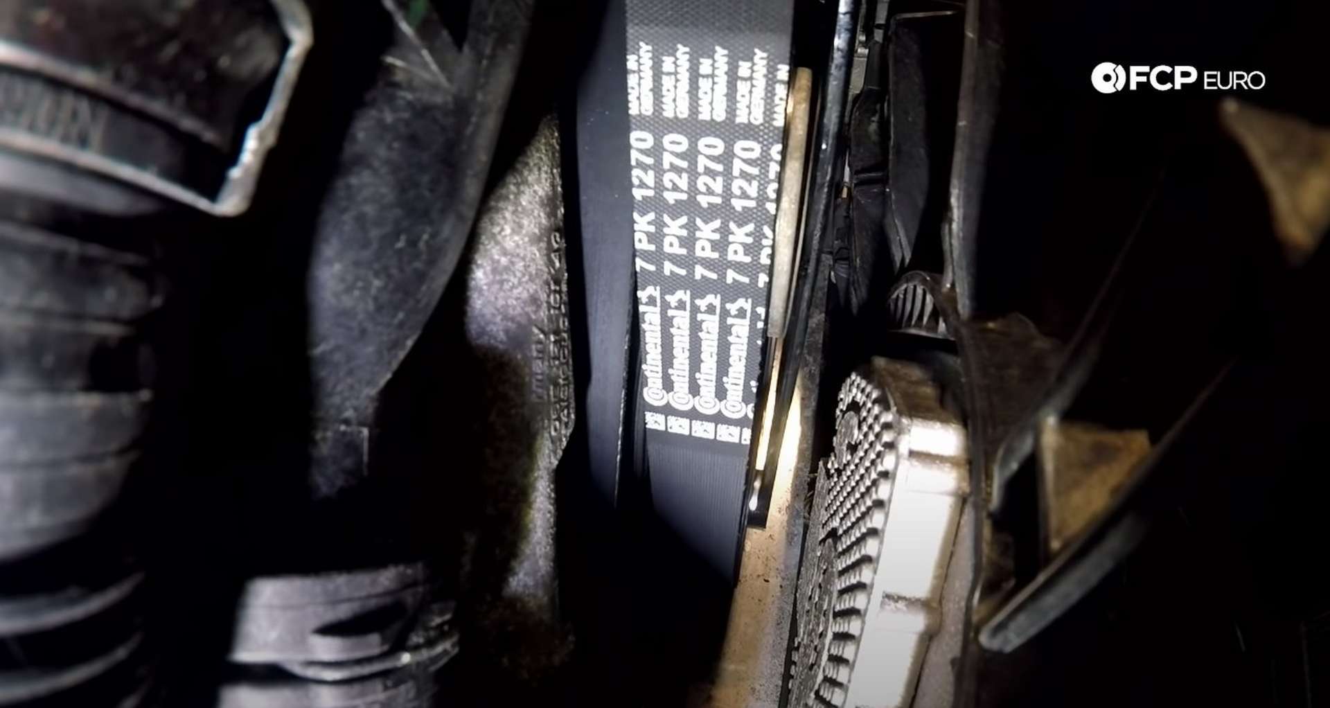
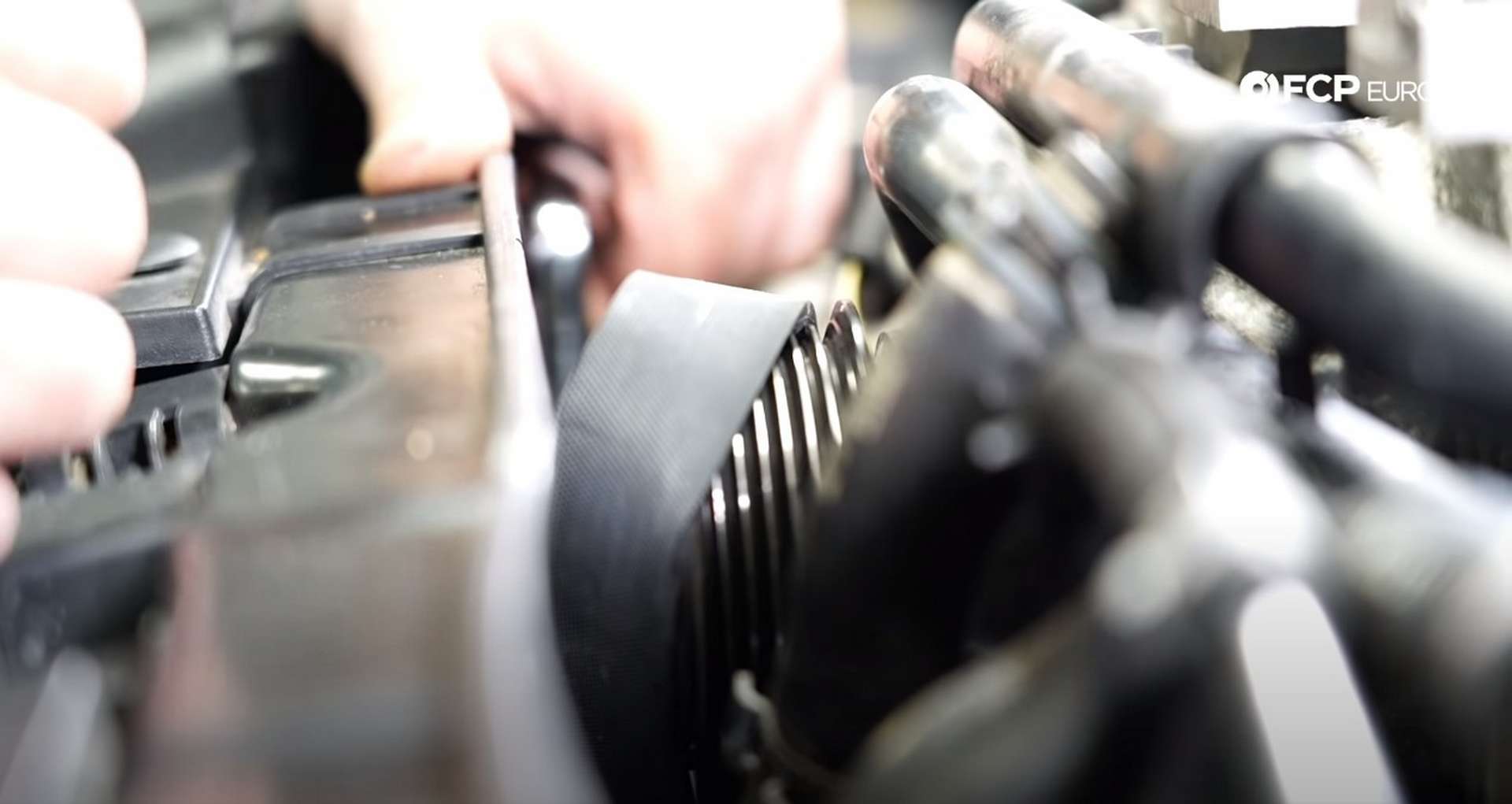
Next, take a long 16mm wrench and slide it between the front of the engine and the radiator to loosen the supercharger belt tensioner. Position the wrench on the tensioner's bolt and rotate it to the right. Then, pull the belt off of the supercharger.
If you are reusing the belt, you can leave it in place after you slip it off of the supercharger. Then, head over to the coolant expansion tank and open the cap to relieve the coolant system of its pressure.
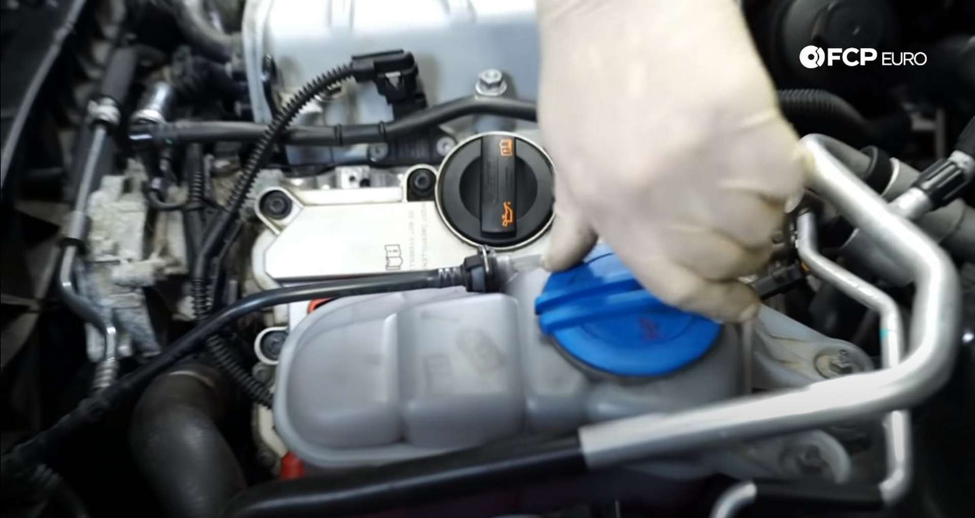
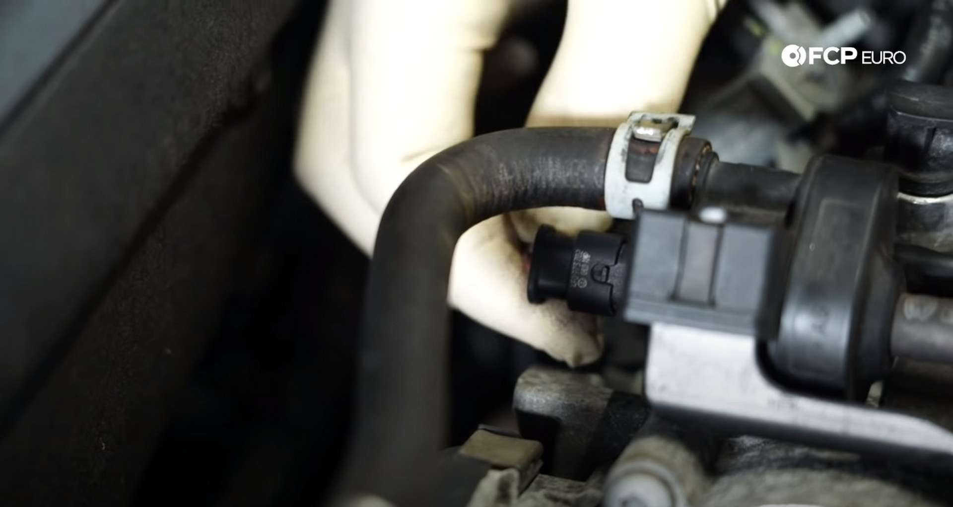
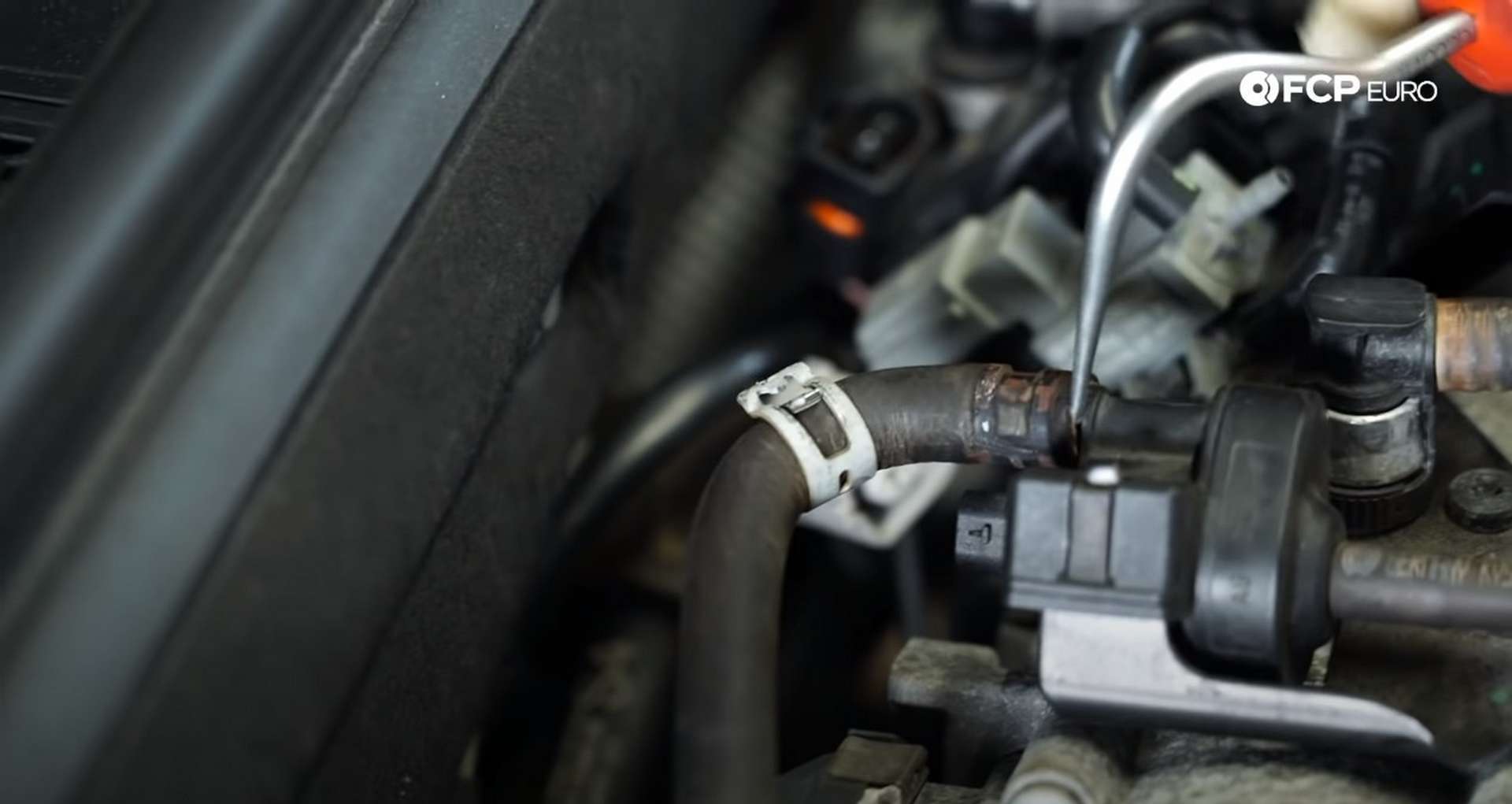
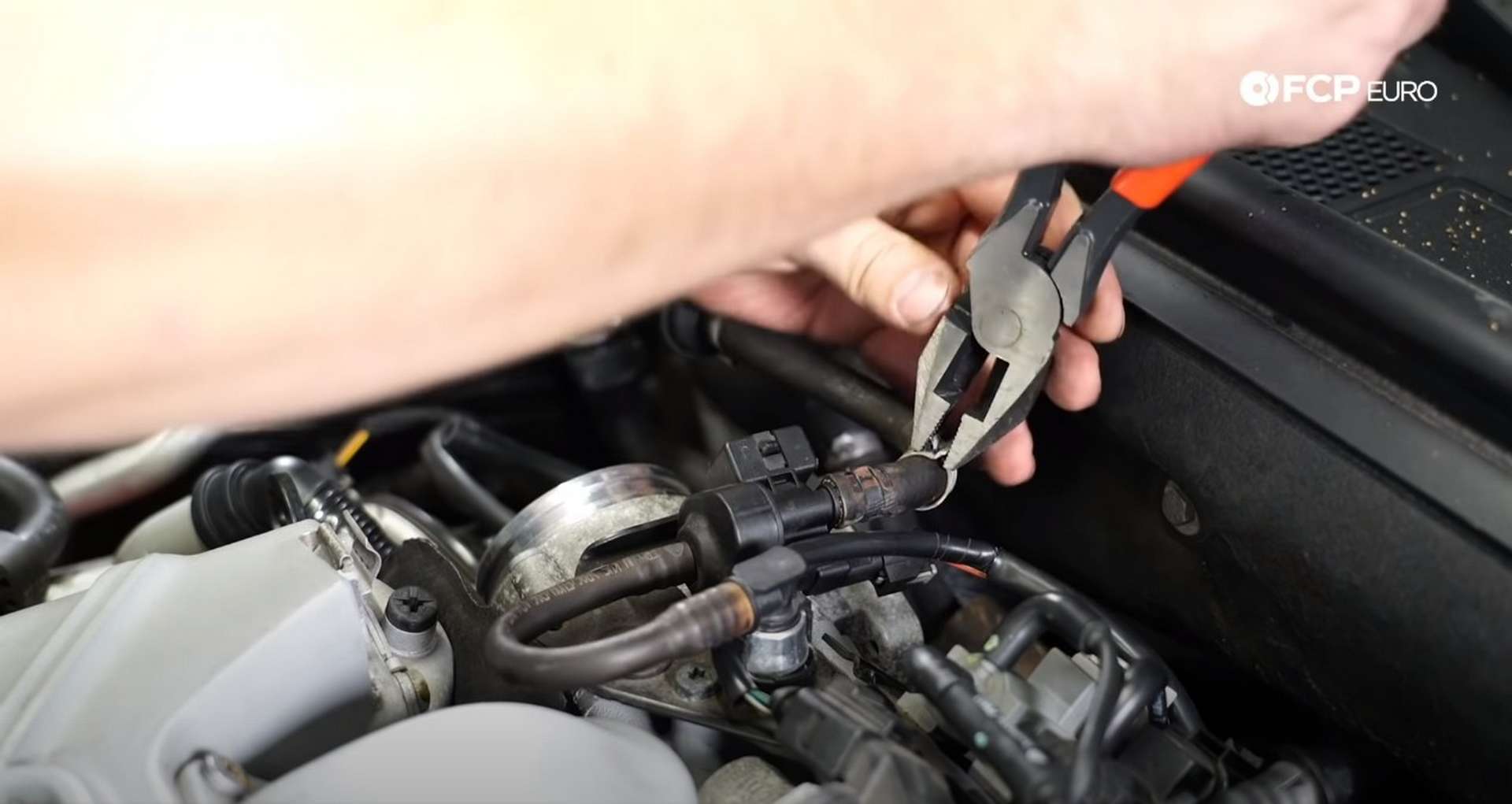
Then, remove the clamps from the two coolant lines on the front of the supercharger. Use a pick to break any coolant build-up preventing the hose from moving before pulling the hose off the supercharger.
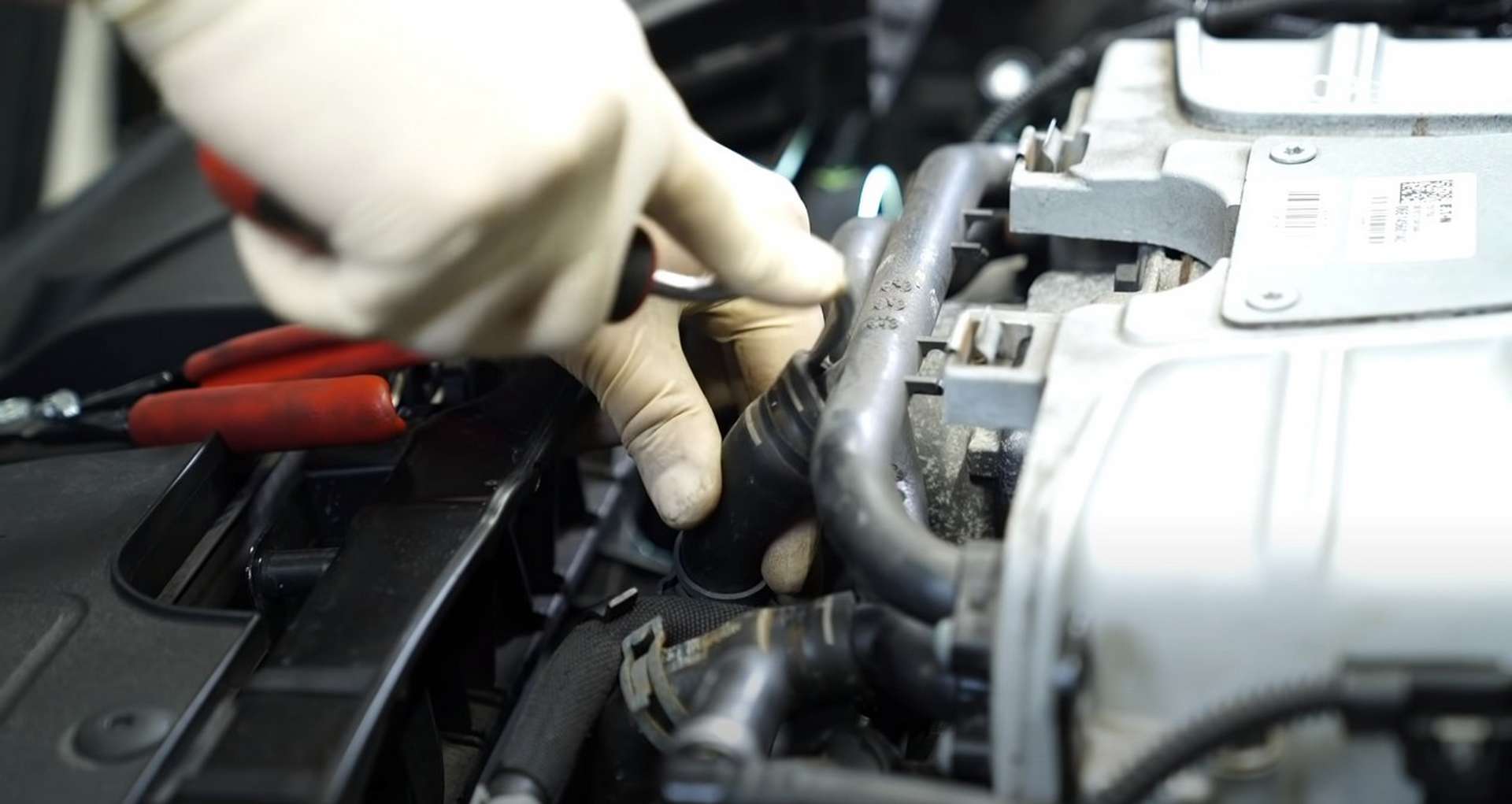
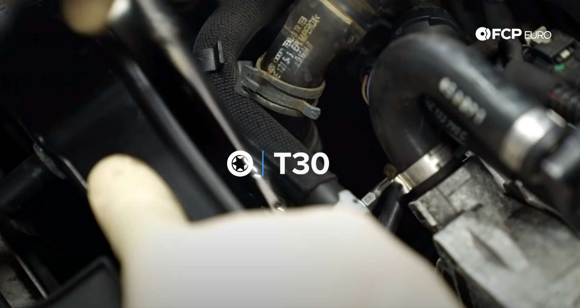
The coolant hoses mount to the engine on the driver's side cylinder head. Use a T30 Torx socket to remove the bolt and allow the hoses to move freely. Then, pull the coolant hoses off of the supercharger.
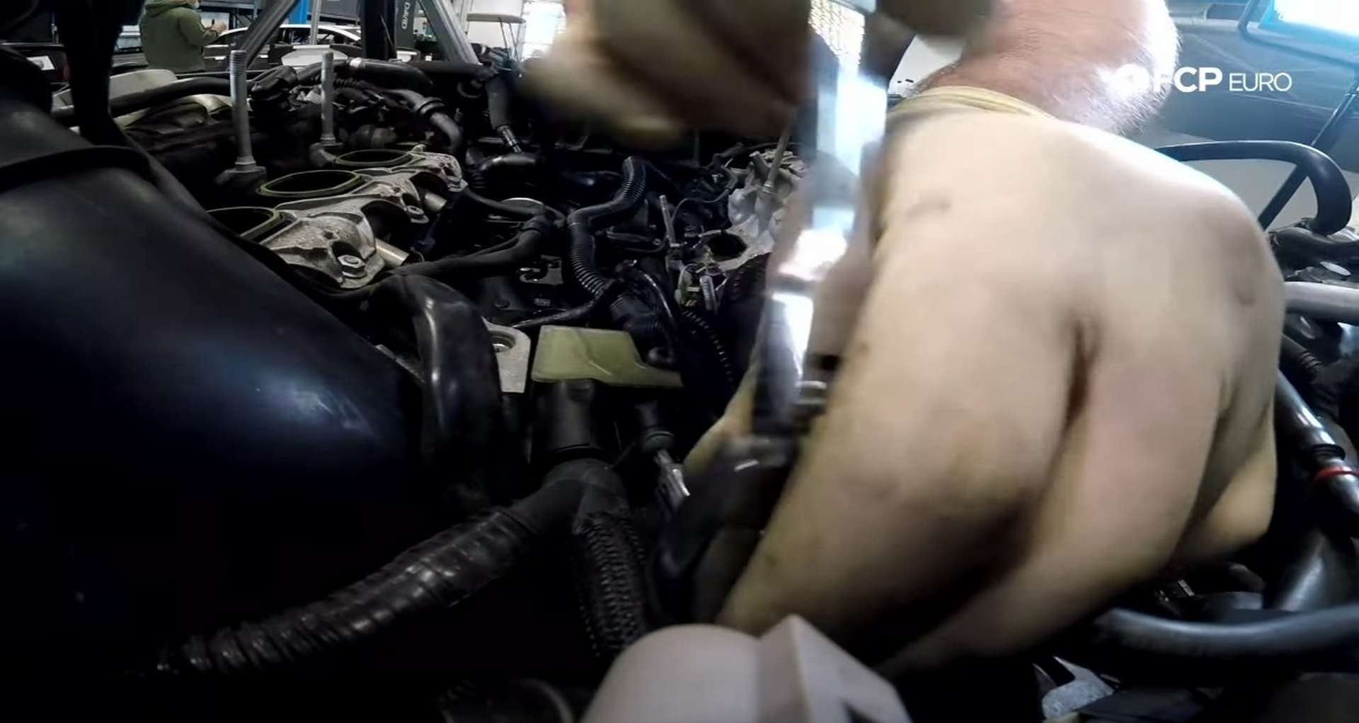
Next, use a 16mm socket to remove the six nuts securing the supercharger to the intake manifold.
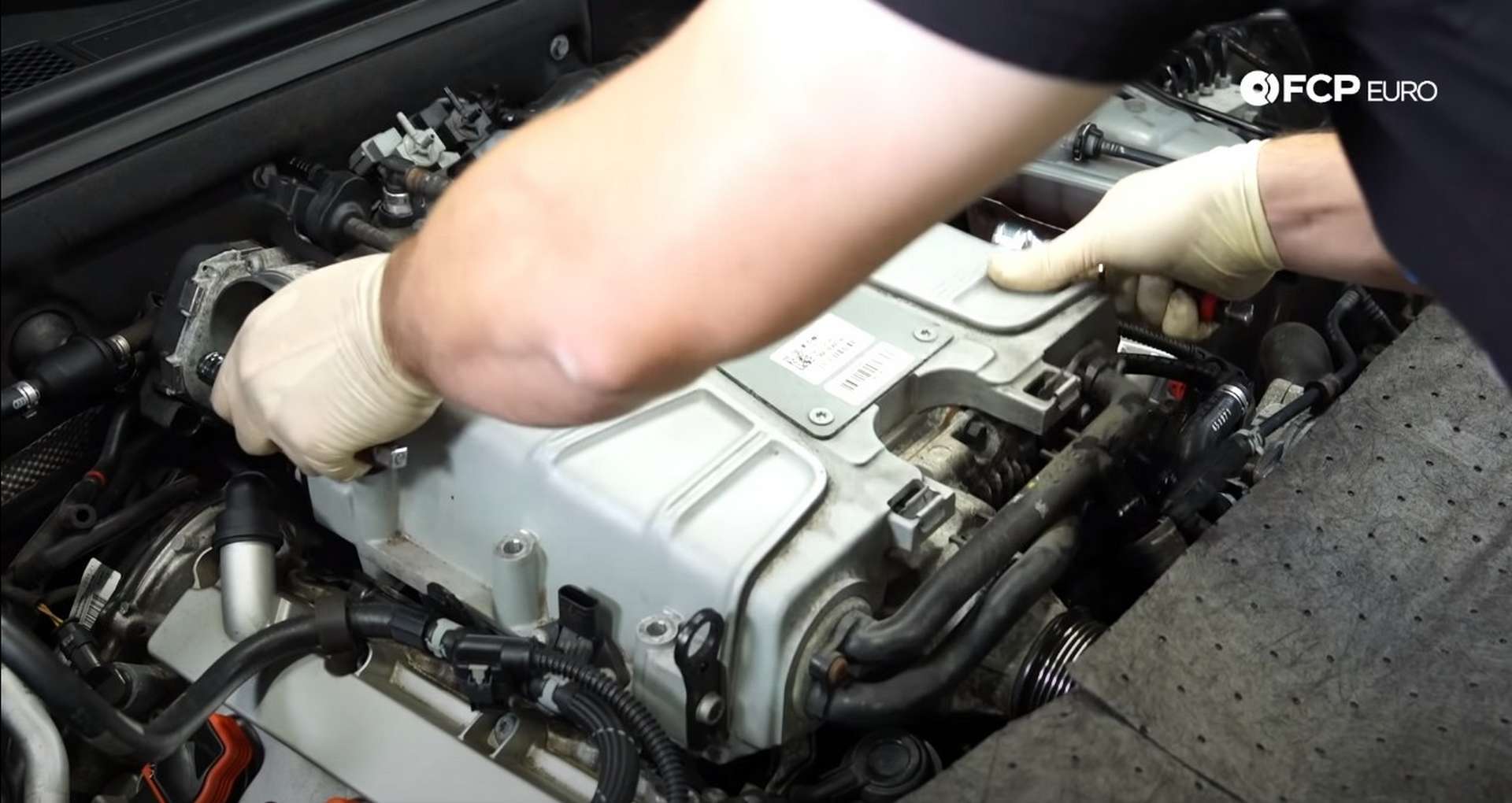
Place some rags or absorbent cloth over the radiator support and front bumper to catch any fluids that may come out of the supercharger as you remove it. Then, place ratchet extensions through the loops on opposite corners of the supercharger to create makeshift handles. Use those handles to lift the supercharger off of the engine.
Step 2: Drain the rest of the coolant
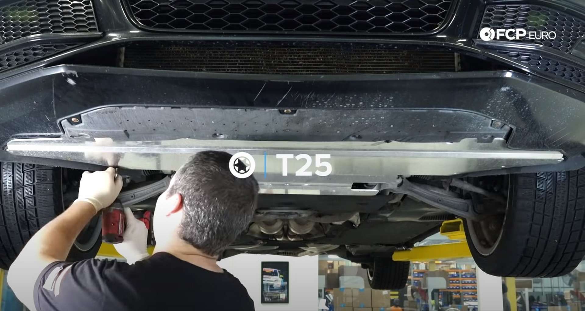
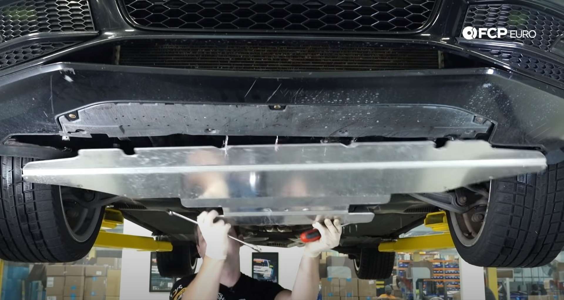
Jack up the front of the car so that you can remove the undertray. Use a T25 Torx bit socket to turn and unlock the fasteners securing the undertray to the chassis. Be aware that dirt, debris, and some coolant from the supercharger will run off of the undertray as you remove it.
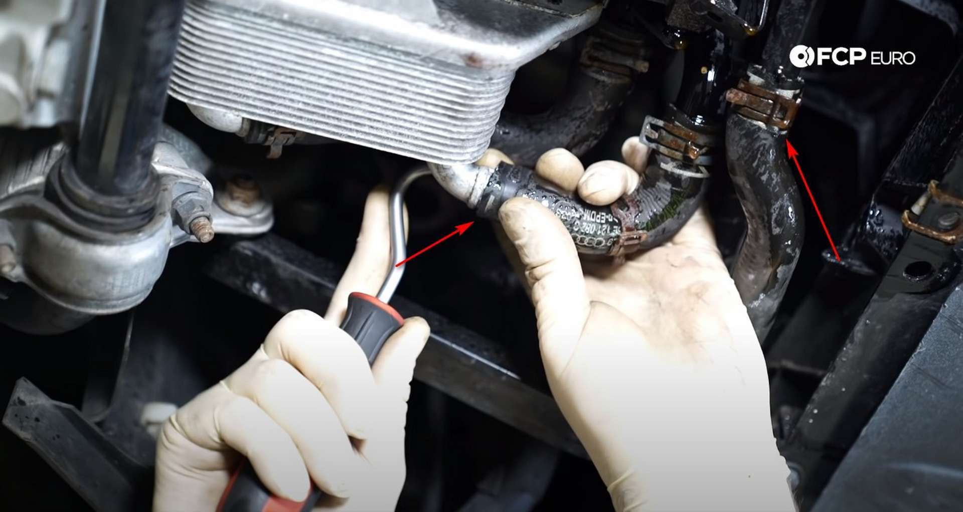
Next, set a drain pan under the heat exchanger. Remove the hose clamp on the coolant hose running to the heat exchanger and the coolant line next to it that runs to the intercooler. Pull the hoses off of the nipples that they are clamped onto and allow all of the coolant to drain out.
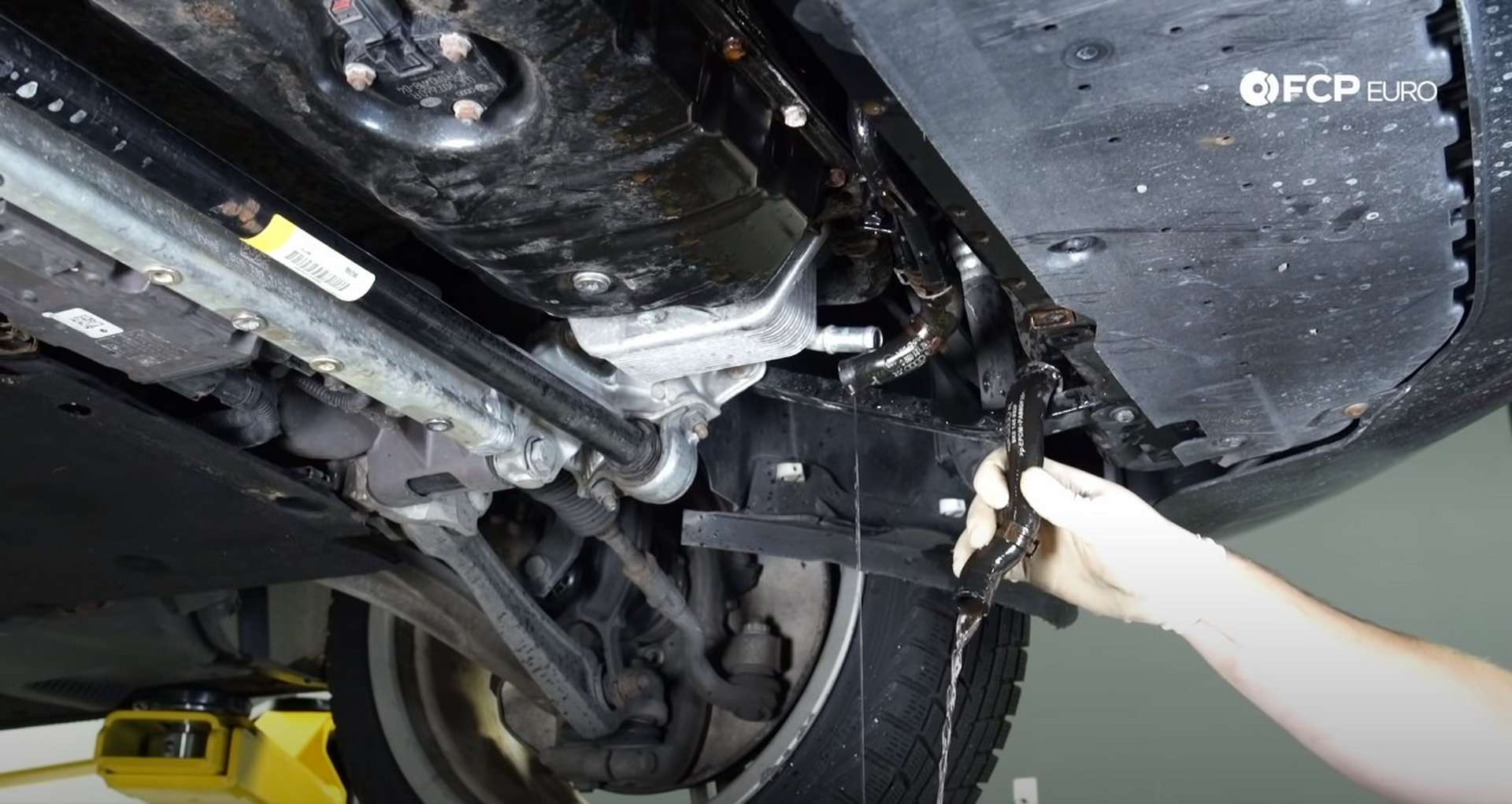
Refit and clamp down the coolant lines once the coolant has stopped draining out.
Step 3: Clear out the valley for PCV replacement
Lower the car down and look around the intake manifold. The chances are that there is a good deal of debris sitting around the manifolds and in the vee of the engine. Use a vacuum to suck out any debris.
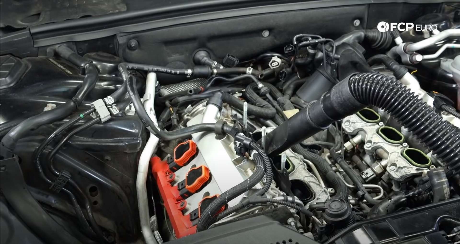
Use compressed air to help push out of tight spaces and into the dirt into the vacuum.
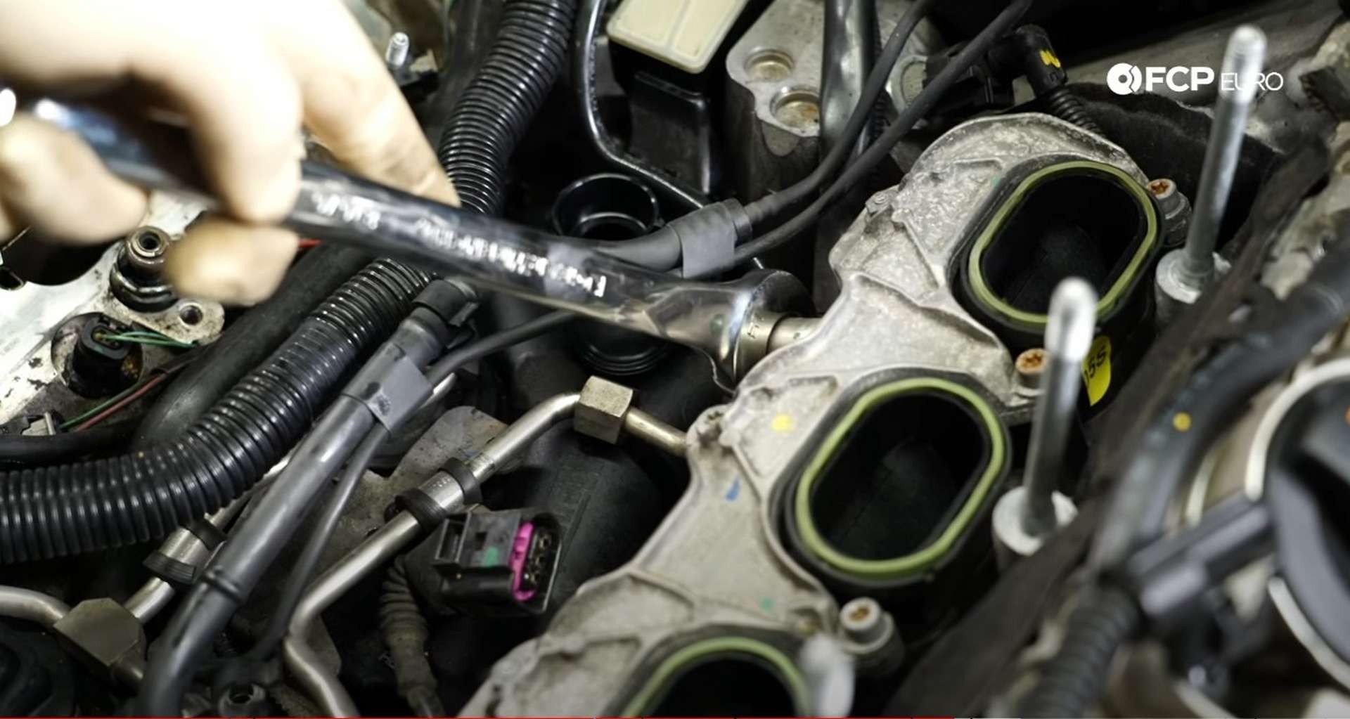
With the dirt vacuumed out, use a 17mm wrench to loosen and remove the manifold's fuel line. Cover the connection with a rag as you loosen the fitting in case any fuel remains under pressure in the line.
Don't open the door after loosening the fuel line, as the car will automatically prime the fuel system. If the fuel system primes while the fuel line is disconnected, fuel will spray out of the line.
Then, move to the front of the manifold and disconnect the short vacuum line.
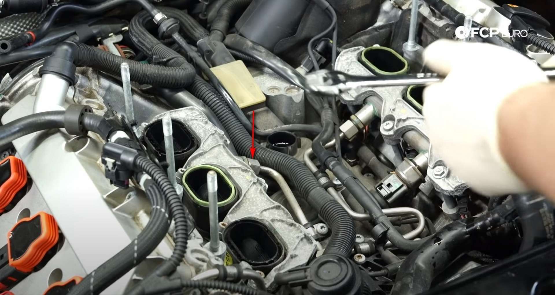
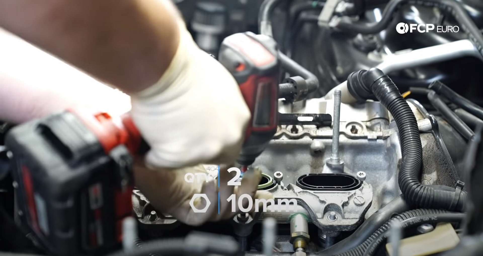
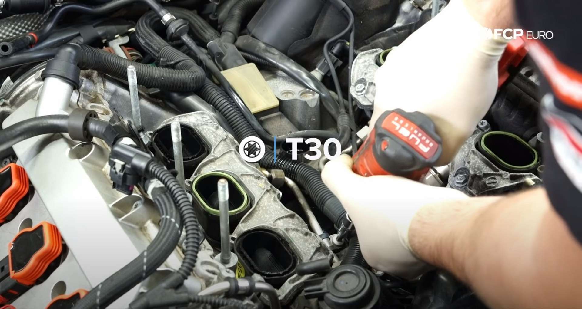
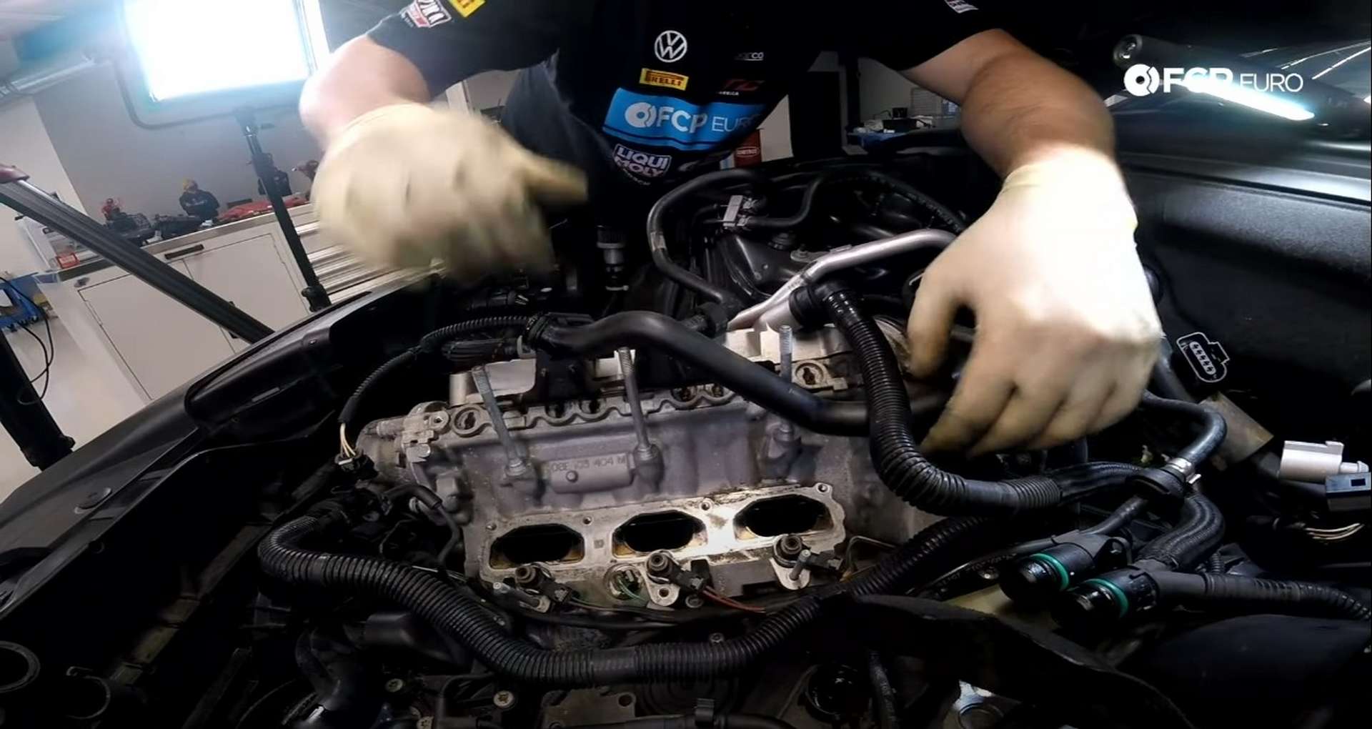
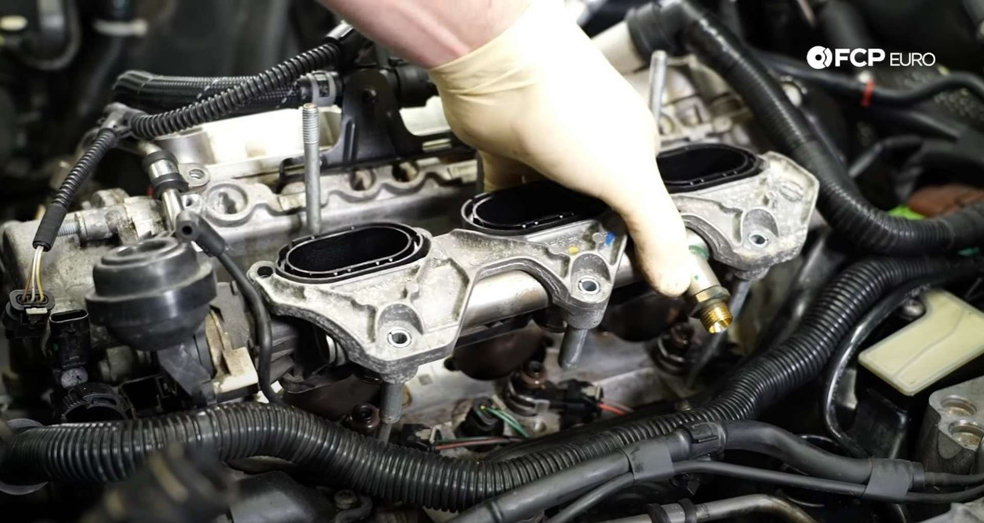
The manifold is bolted to the cylinder head by two nuts and five bolts. Use a 10mm socket to remove the two nuts and a T30 Torx bit to remove the five bolts. Then, use the T30 Torx to remove the bolt.
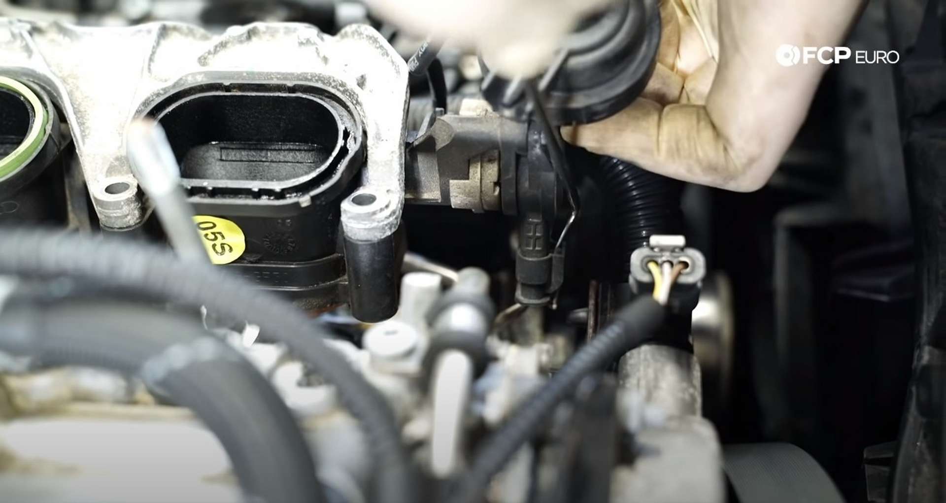
There is an electrical connection for a sensor at the front of the manifold near the disconnected vacuum line. Lift the manifold out slightly to bring the connection into open space, Then use a pick to push down on the white locking tab to unlock the connection.
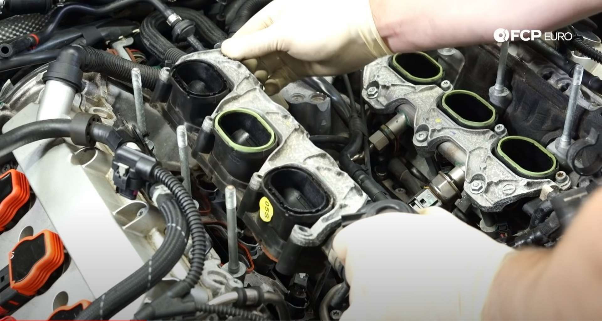
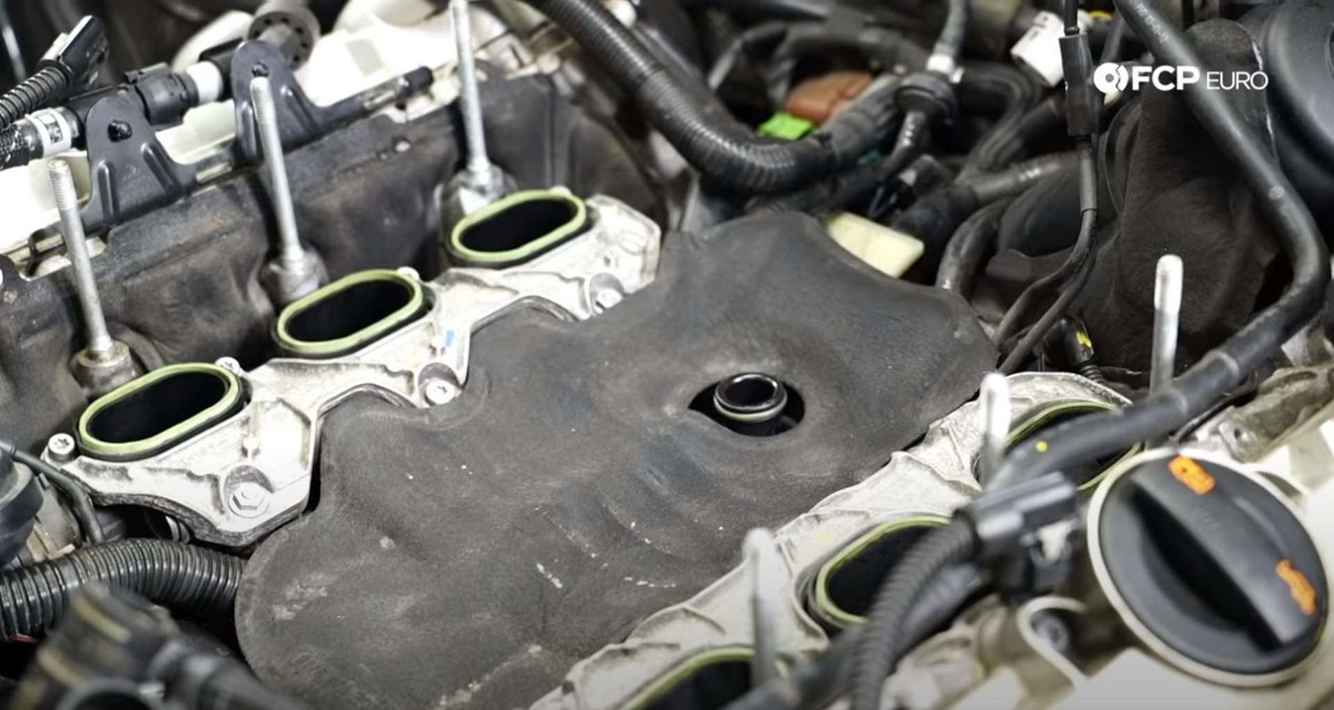
With the manifold off of the cylinder head, examine the area around the ports. If there are more sand and dirt around intake ports, use the vacuum to eliminate it.
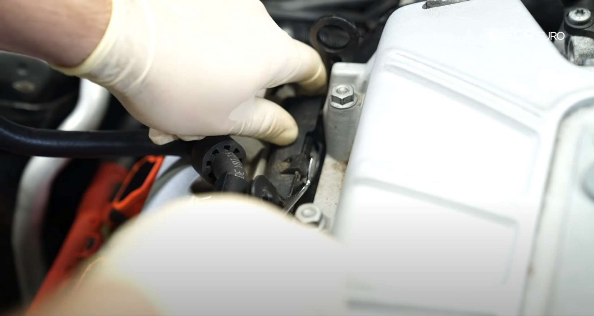
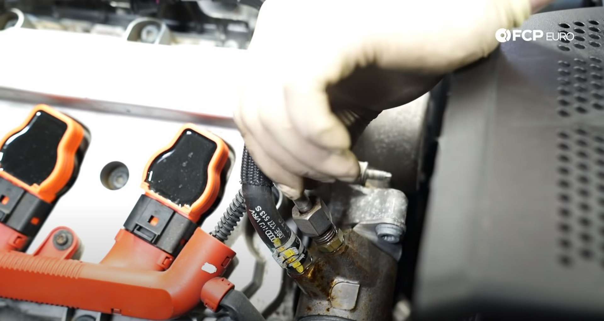
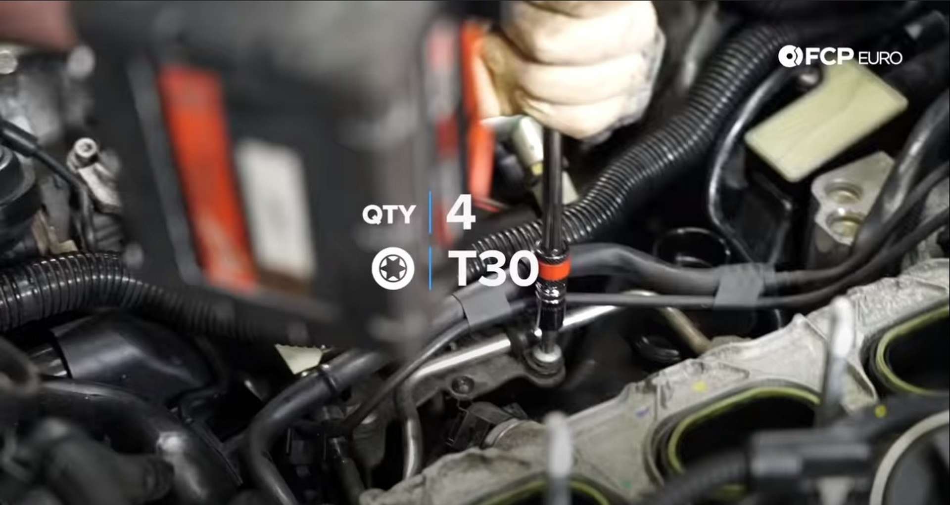
Next, use a 17mm wrench to disconnect the fuel line from the other bank's manifold and use a 27mm wrench to remove the fuel pressure sensor. Follow that fuel line over to the passenger's side cylinder head and remove the three T30 bolts that secure the fuel line to the engine.
Once the fuel line is free of the block, use a 10mm wrench to remove the two nuts for the high-pressure fuel pump cover on the front of the passenger's side cylinder head.
Use a 17mm wrench to disconnect the fuel line that runs to the high-pressure fuel pump. Then, remove the two nuts and five bolts from the remaining intake manifold.
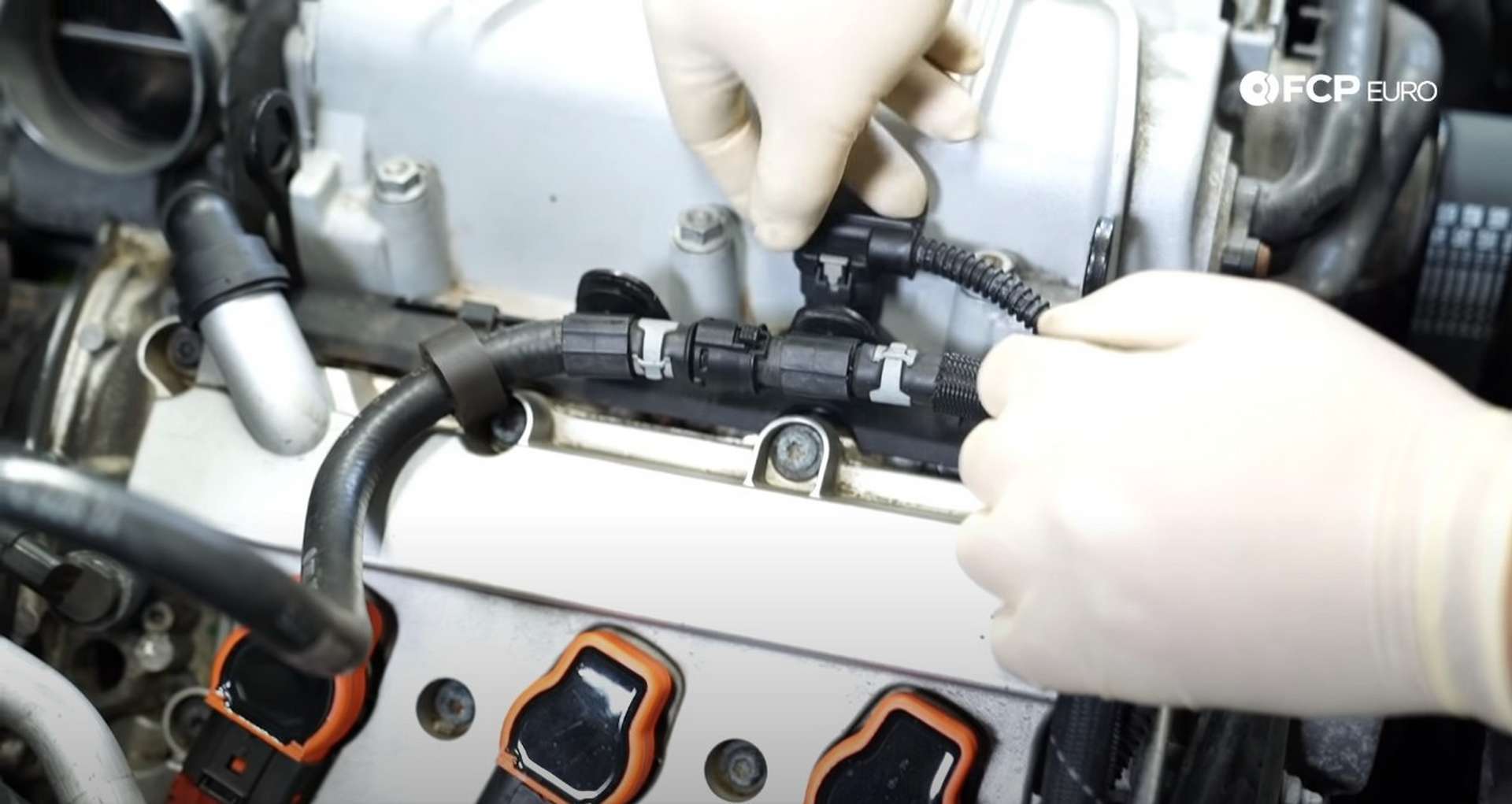
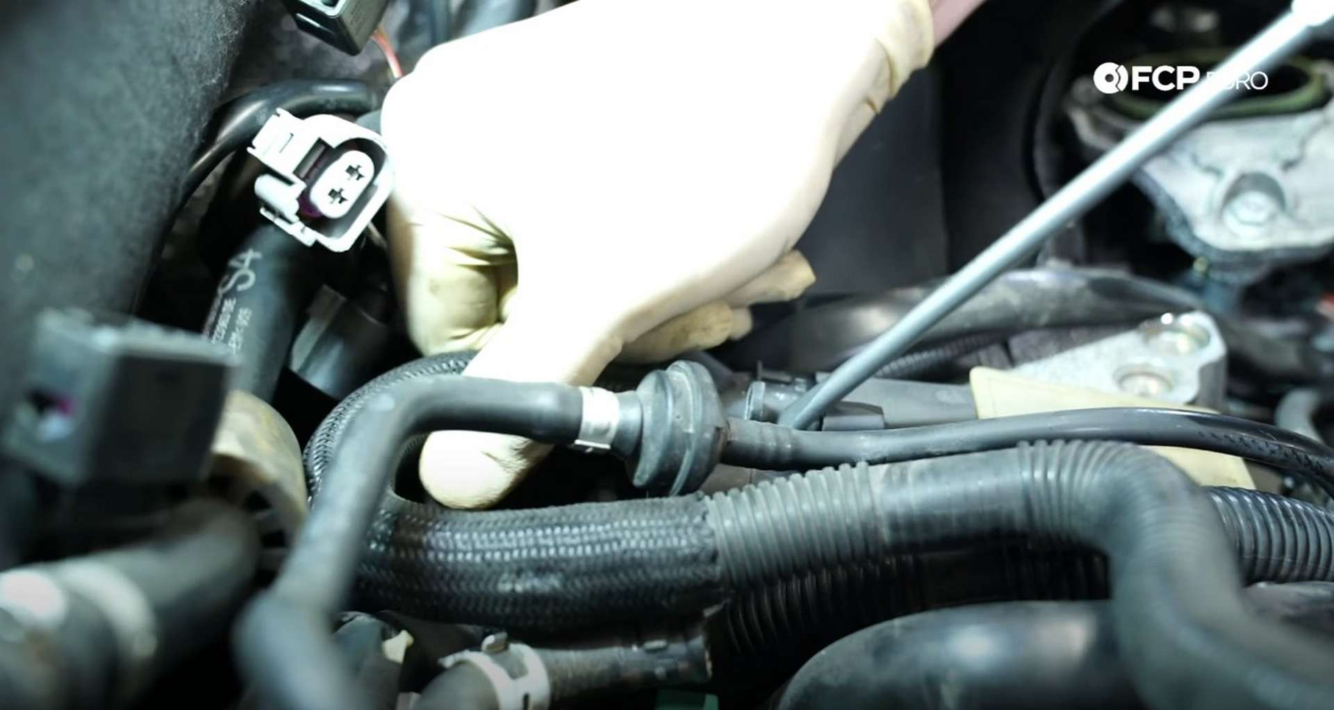
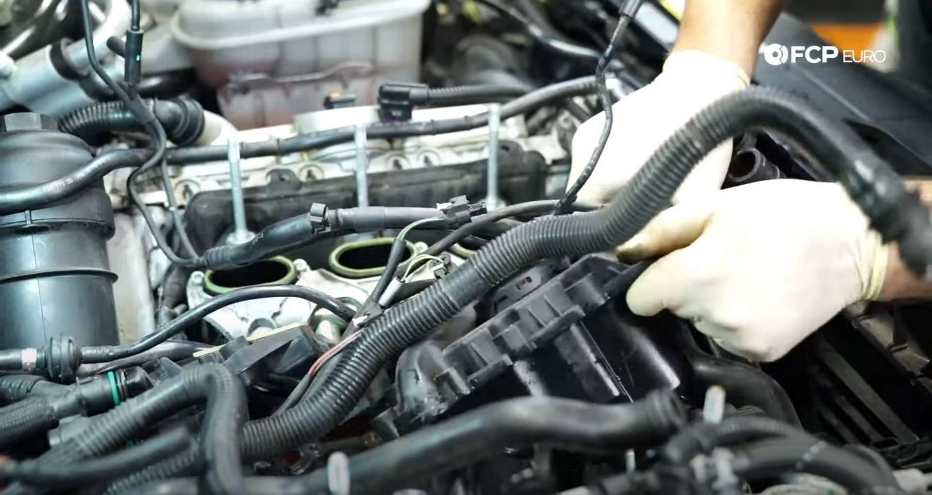
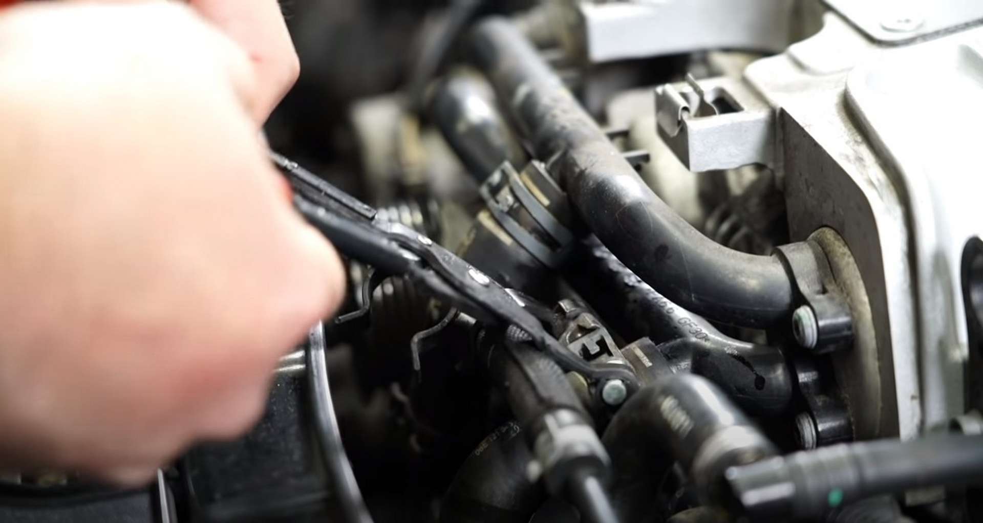
Next, use a pick to disconnect the secondary air-line. The line connects to the front of the engine near the high-pressure fuel pump and runs through the engine's valley, over the PCV. Use a pick to gently pry on the tabs of the airline to disconnect it.
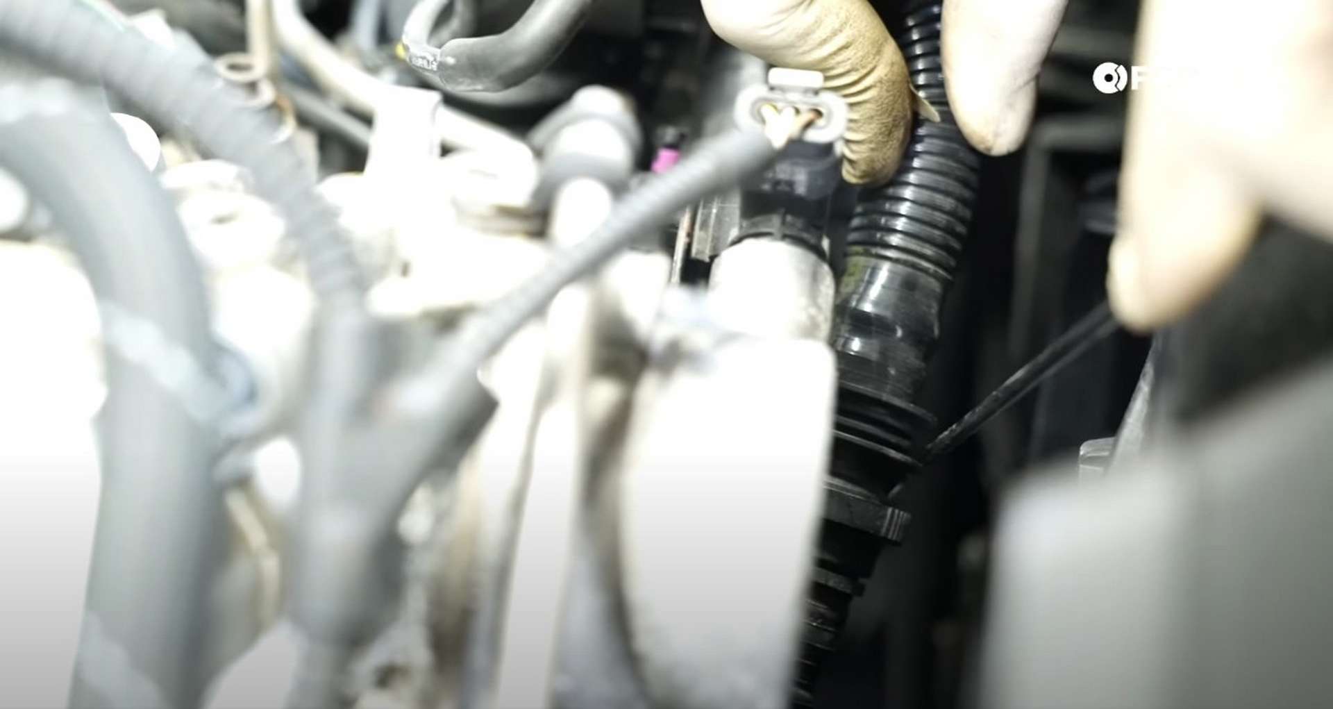
Unclip the secondary air-line and any other hoses and lines from the fuel hardlines for the intake manifolds. Then, remove the fuel hardlines from the valley of the engine.
Use a fluid extractor or rags to clean up any fuel that came out of the hard-lines.
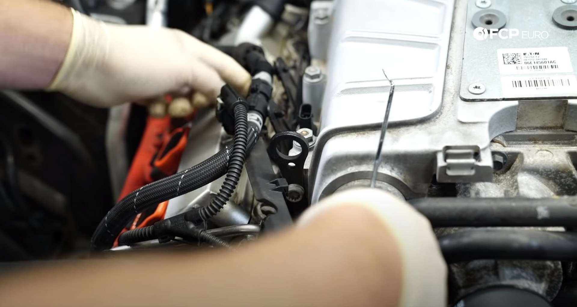
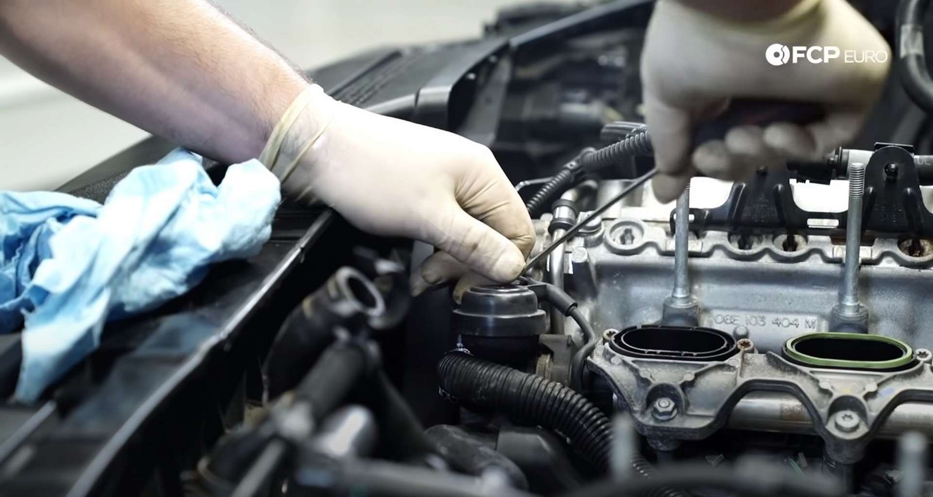
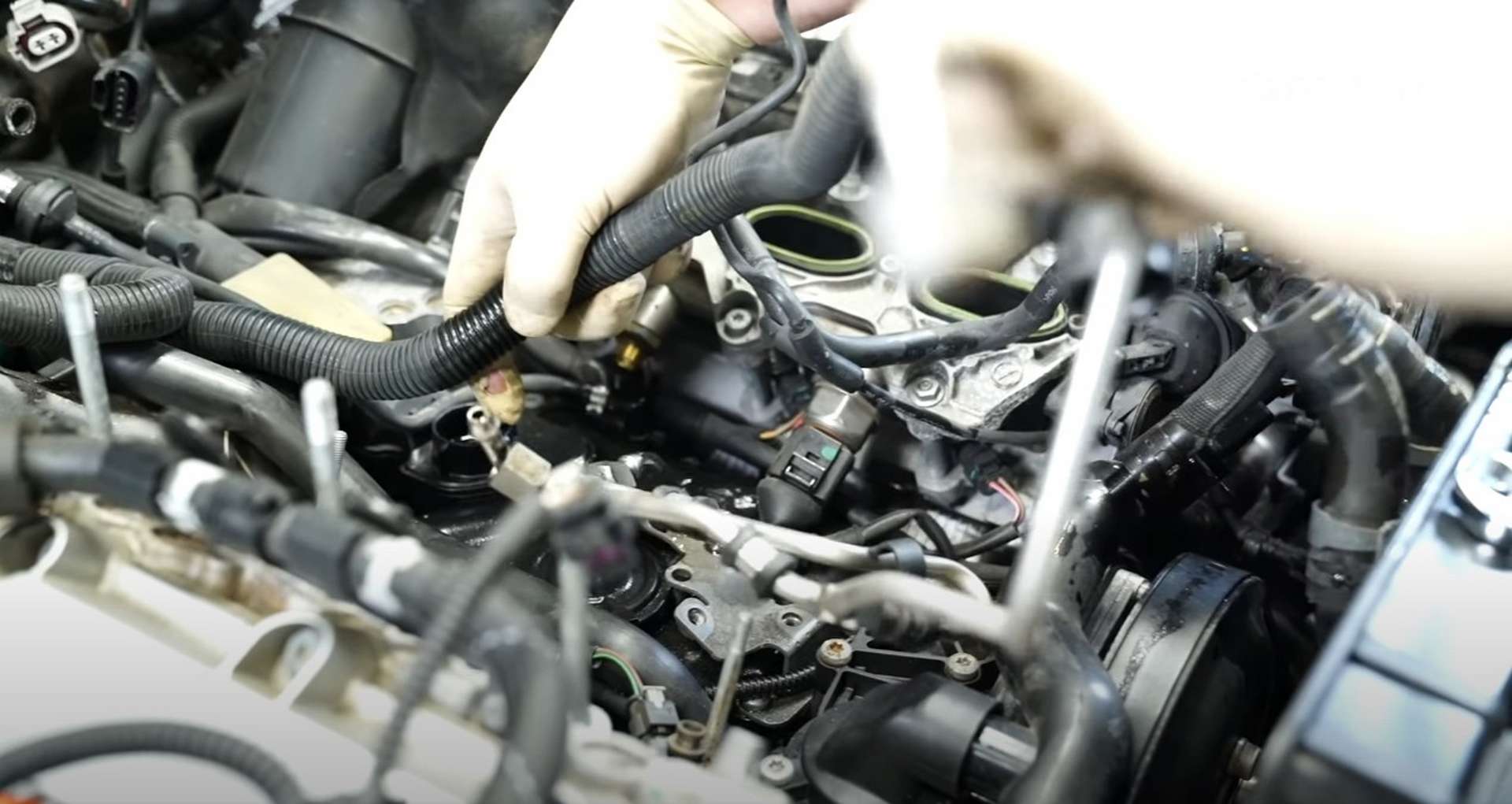
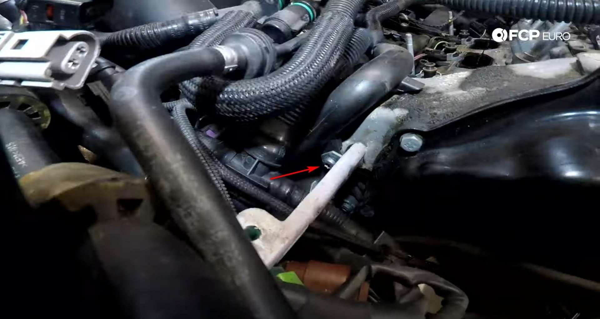
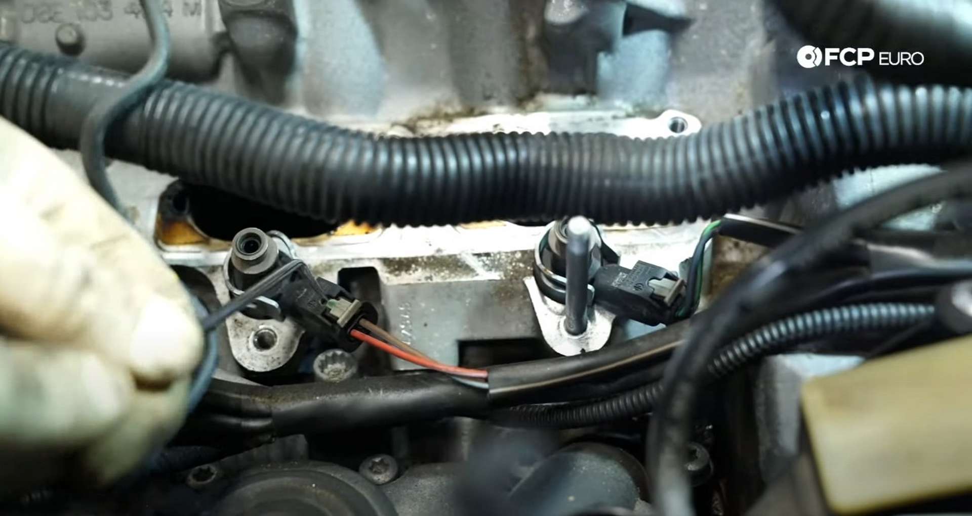
Oil breather lines run from the backs of the cylinder heads to the PCV. Use a T20 bit socket or driver to remove the bolt that secures the PCV housing's breather lines. Then, gently use a flathead screwdriver to push the lines out of the housing.
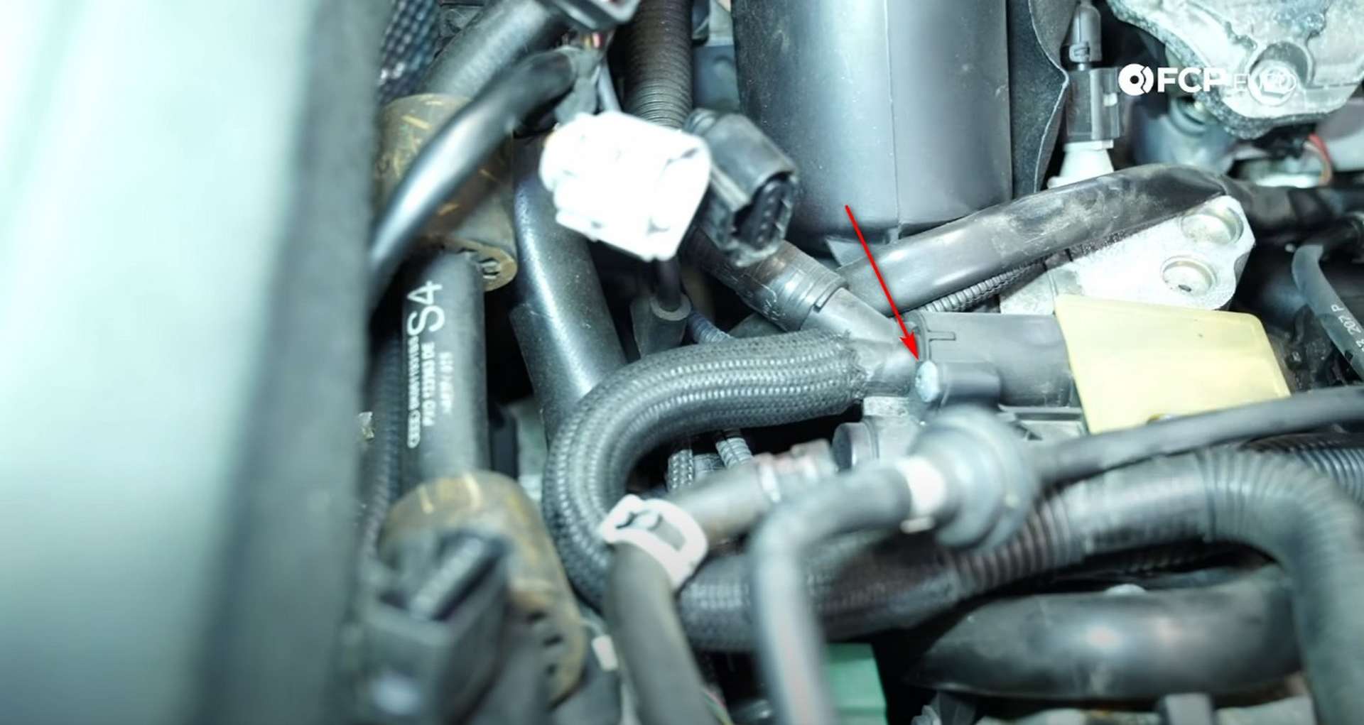
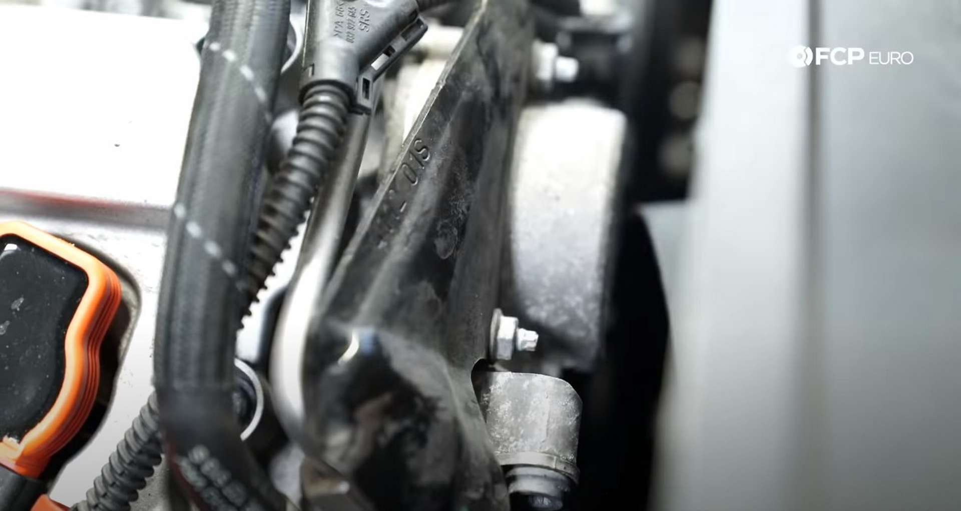
In that same area is a mounting bolt for a coolant hard-pipe. Push the green and brown connections out of the metal mount to gain access to the bolt, then use a T30 bit to remove the bolt.
Pull the pipe out of its connection at the front of the engine before lifting it and positioning it on the intake manifold stud.
Lastly, disconnect the injector harness from the passenger's side injectors. Use a pick to help unlock the injector connections.
Step 4: Replace the PCV/AOS
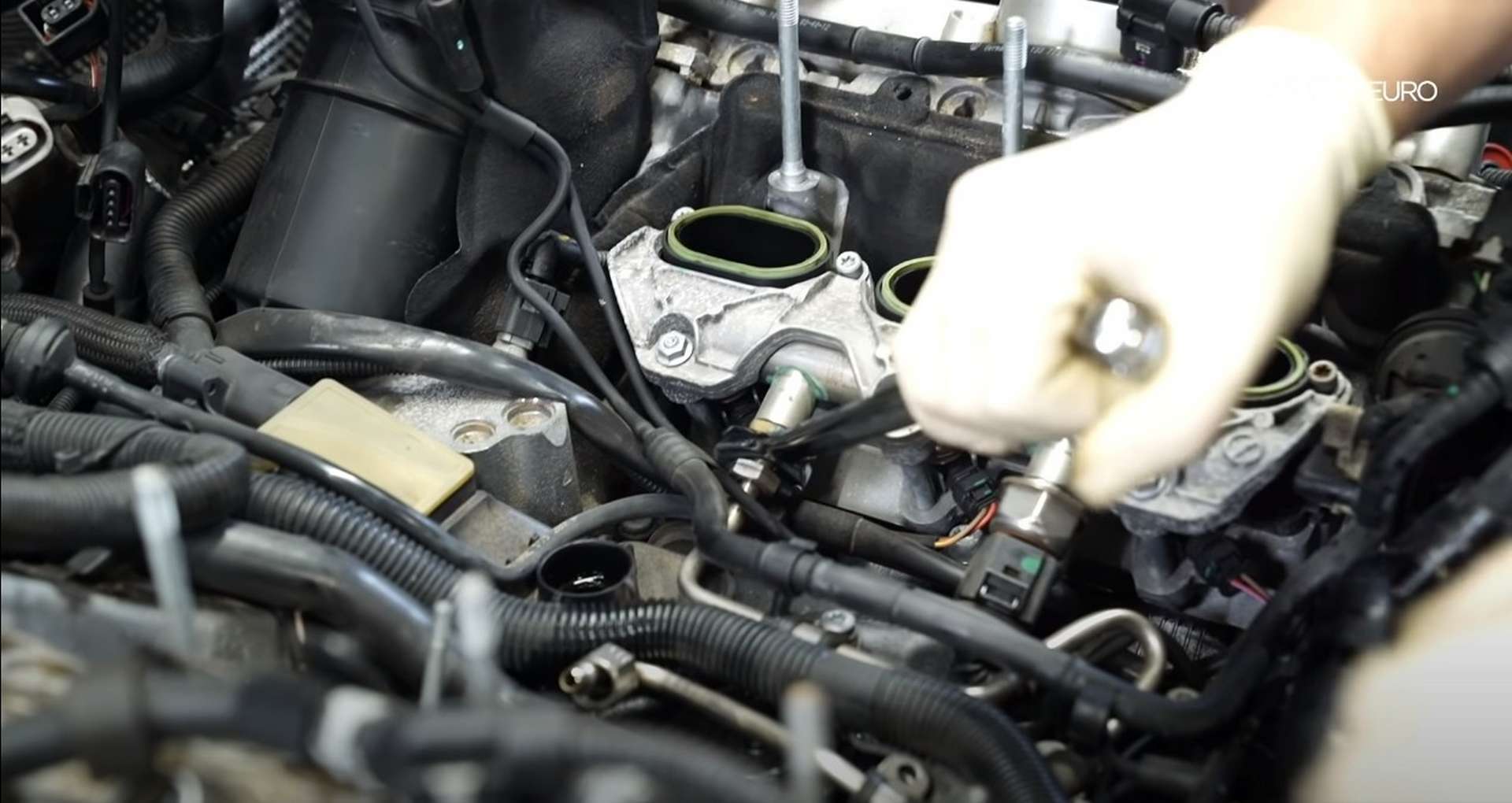
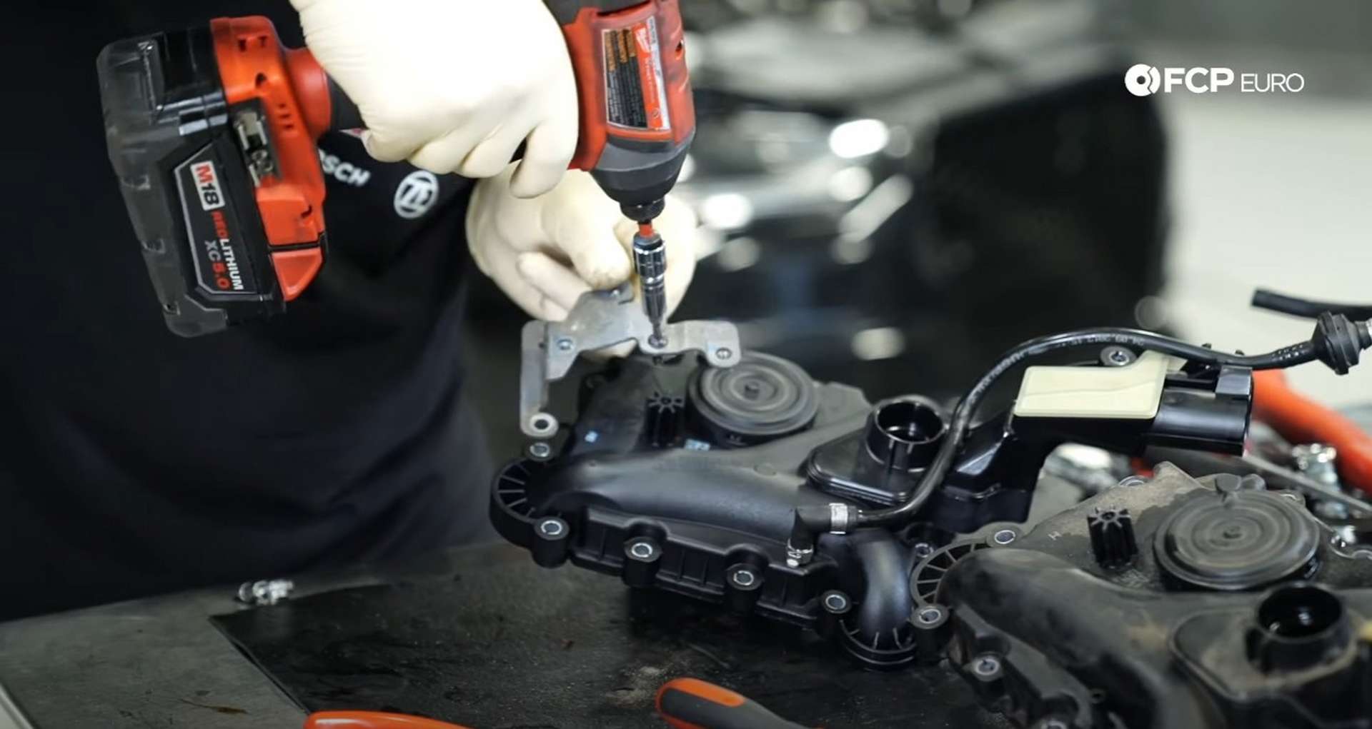
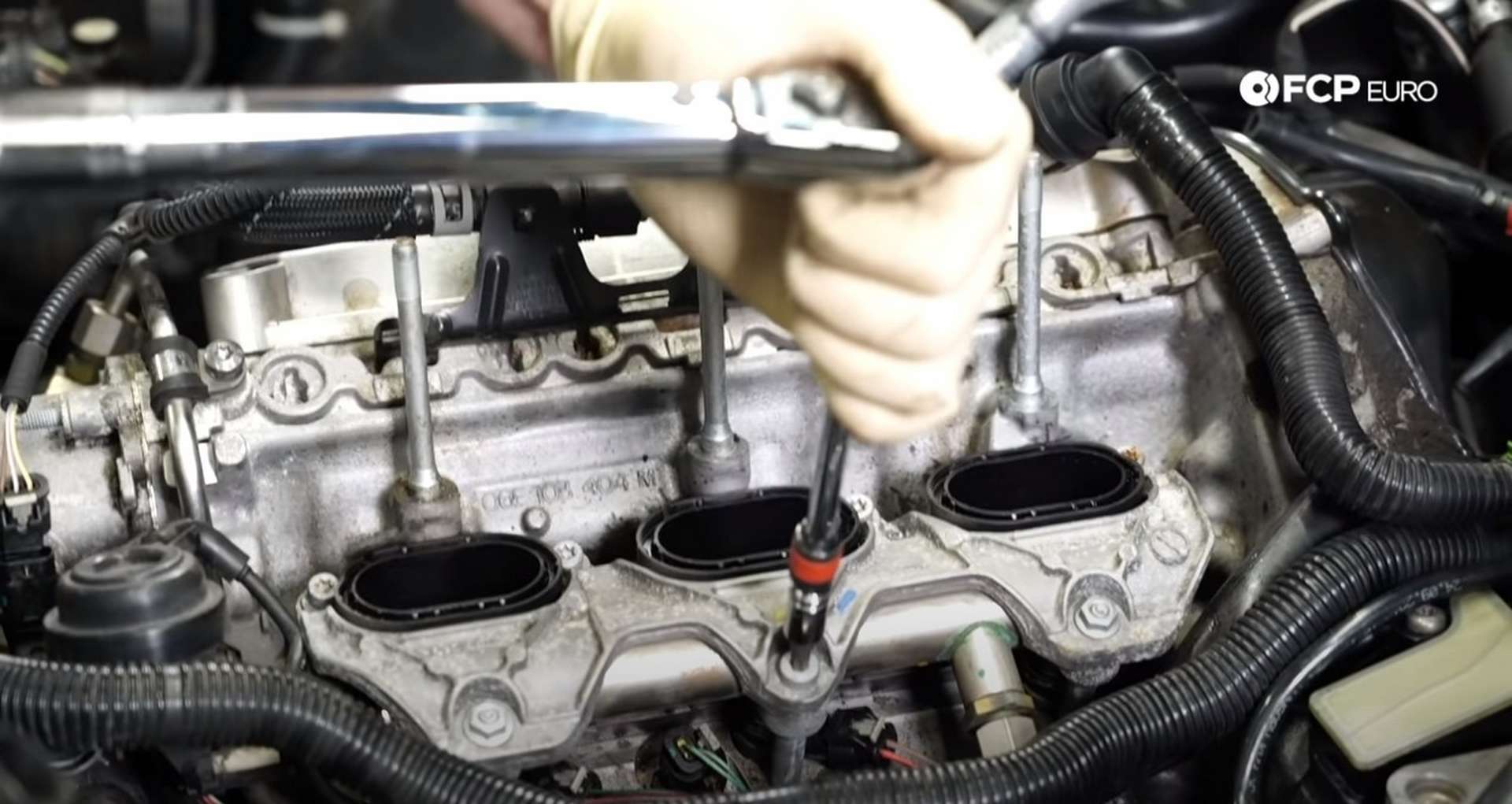
Use a T30 bit to remove the PCV housing's fourteen mounting bolts. Then, use a 19mm wrench to remove the male end fuel line fitting from the driver's side intake manifold.
Grab the PCV housing and remove it from the engine. Remove the hose and bracket from the old PCV unit and install them onto the new one.
Use a rag to wipe any debris off of the PCV's mating surface on the engine and then install the new PCV. Take your time and be careful when you install the new PCV to ensure no hoses, lines, or wires get trapped under it. Start all of the bolts by hand to prevent any cross-threading. Then use a T30 bit and a torque wrench to torque them to 9Nm.
Next, reconnect the injector harness. Use a pick to remove the o-ring from the coolant pipe and replace it with a new one. Seat the pipe back into place. With the pipe in place, thread in its
T30 mounting bolt at the back of the engine. Refit the brown and green connections to the metal bracket if you removed them.
After that, refit the breather hoses into the PCV unit. Then, thread in the securing bolt and tighten it with a T20 bit.
Step 5: Reinstall the intake manifold
Take the fuel hardline and fit it into position in the engine's valley. Then thread in the fuel line fitting on the driver's side intake manifold. Use a 19mm wrench to torque it to 40Nm.
Next, loosely reconnect the hard-line to the fuel pump and the intake manifold. Then, reinstall the passenger's side intake manifold.
First, plug in the vacuum line and the position sensor connector. Then seat the manifold onto the fuel injectors and mounting studs. As you push the manifold onto the cylinder head, manually move the linkage for the runners' flaps to prevent the flaps from getting jammed on the intake port dividers.
Tighten all of the fuel hardline connections with a 17mm wrench. Then secure the line to the engine by tightening the four hardline mounting bolts with a T30 Torx socket or screwdriver. After that, torque the hardline connections to 27Nm.
Then, fasten the manifold to the head. Install the larger T30 bolt in the hole between the studs and install the smaller T30 bolts in the four spots above the ports. Use the two 10mm nuts on the studs. Torque all of the mounting hardware to 9Nm.
Thread in the fuel pressure sensor and torque it to 22Nm with a 27mm wrench. Plug in the sensor and open the door to the car. Opening the door will prime the fuel system, sending fuel through the lines you just tightened. The fuel priming the system will show any leaks that are present. After that, reclip all of the vacuum lines back to the fuel hardline.
Lastly, reinstall the protective plate that covers the high-pressure fuel pump. Use a 10mm socket to tighten the two nuts that secure the plate to the engine.
Step 6: Reinstall the supercharger
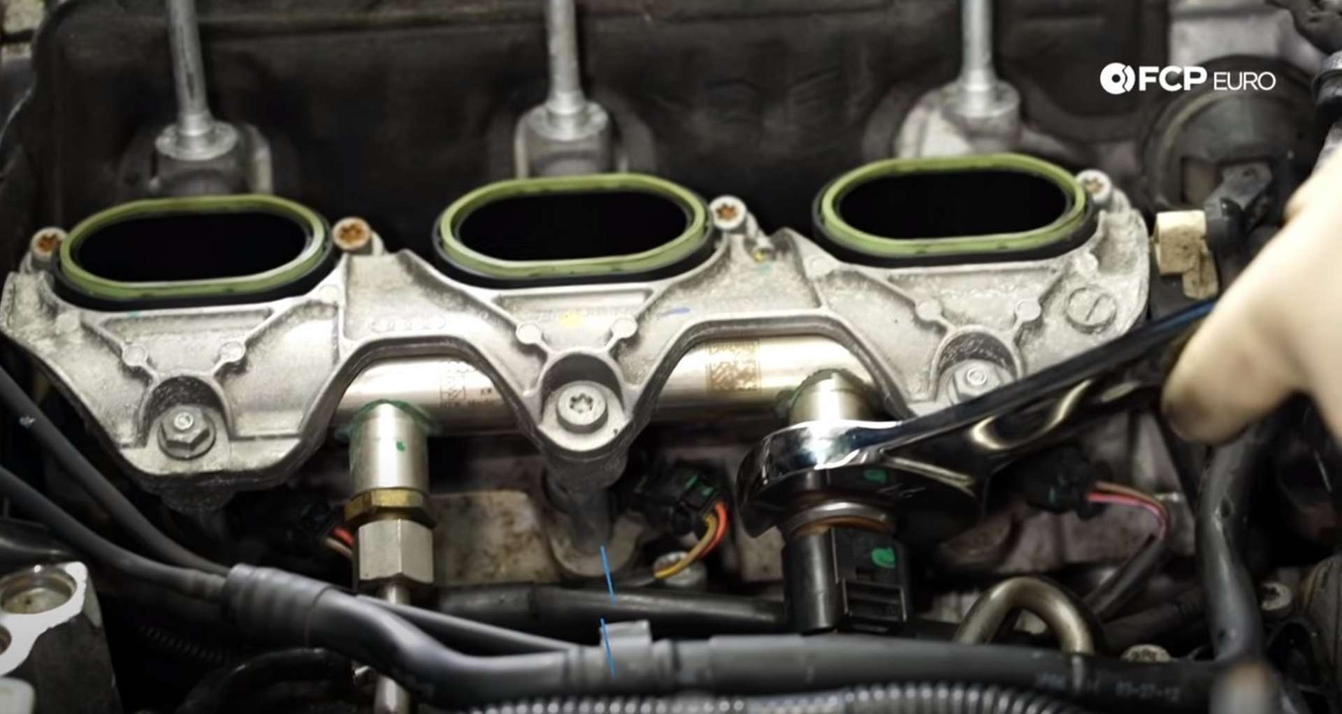
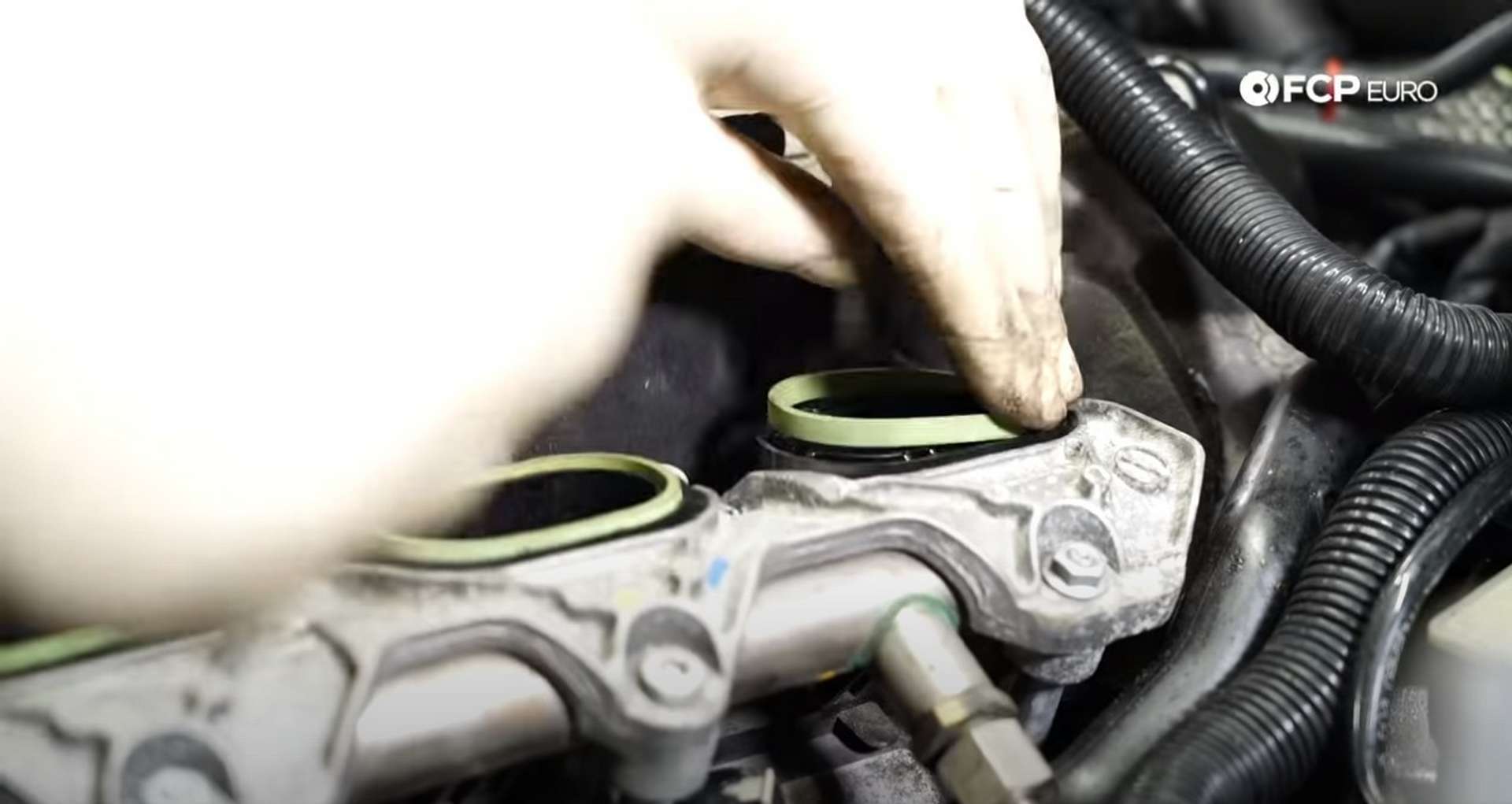
First, reconnect the secondary air-line and refit any insulation pieces that you may have removed during the job. Then, remove the old, green supercharger gaskets and replace them with new ones.
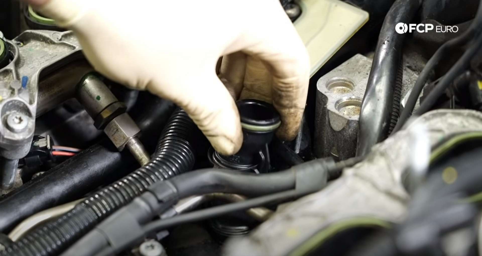
Next, lightly lubricate the o-rings of the new supercharger breather pipe and press it into the engine. Then lay the insulating engine valley cover over it.
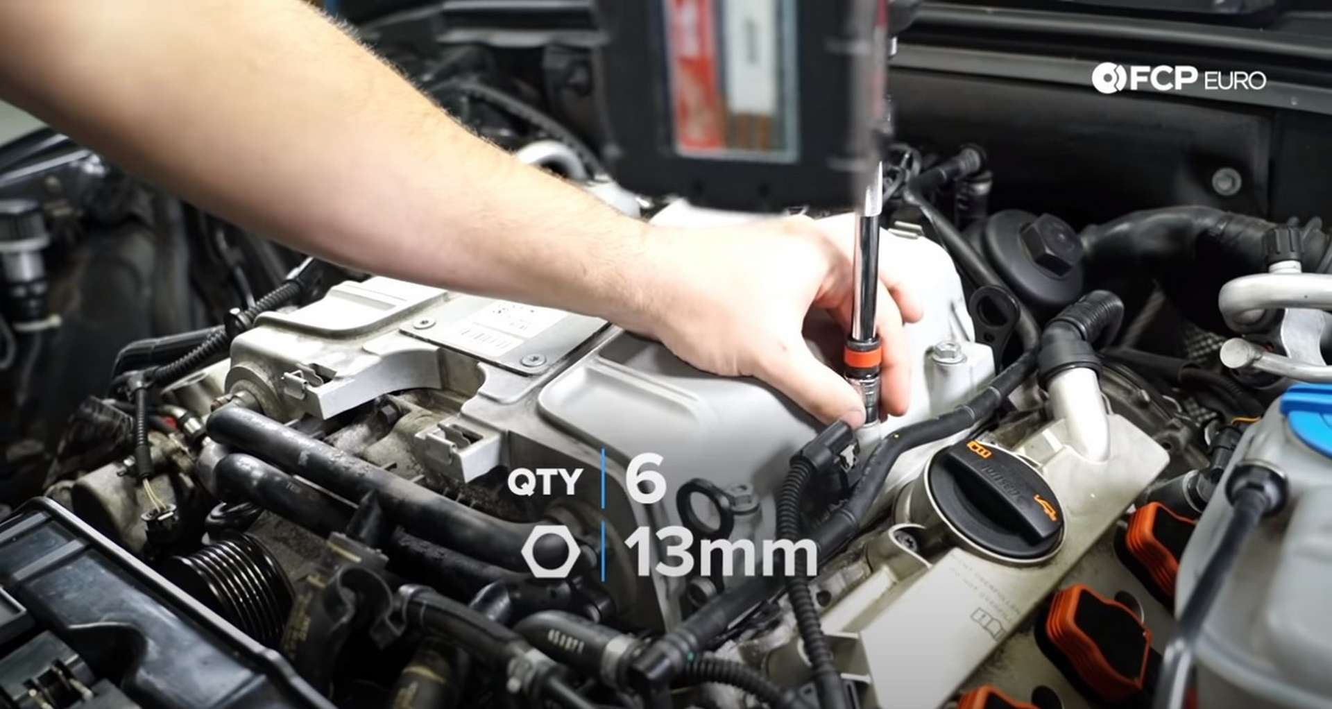
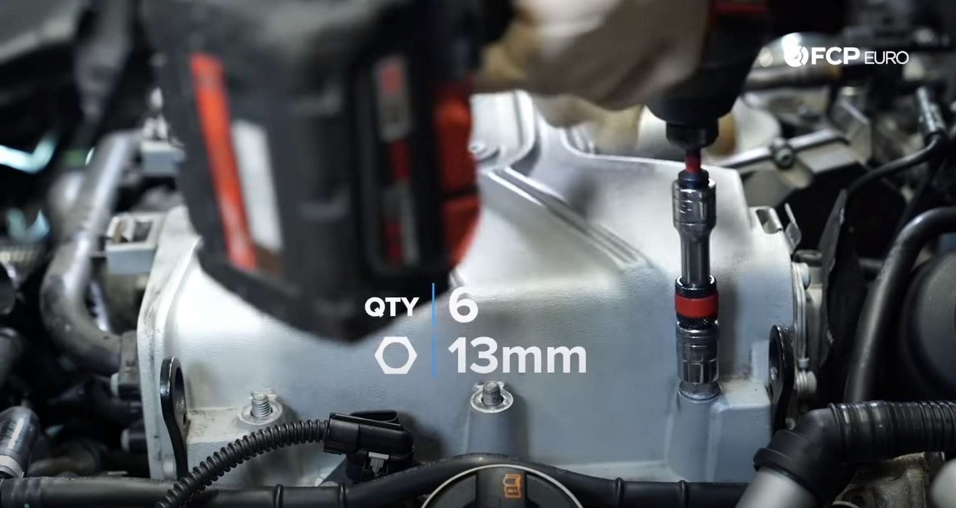
Now, grab the supercharger and seat it onto the engine. Ensure that all of your vacuum lines and sensor wires for the back of the supercharger are not getting pinched or trapped under it as you press it onto the engine. Then, thread on the six 13mm nuts onto the supercharger mounting studs.
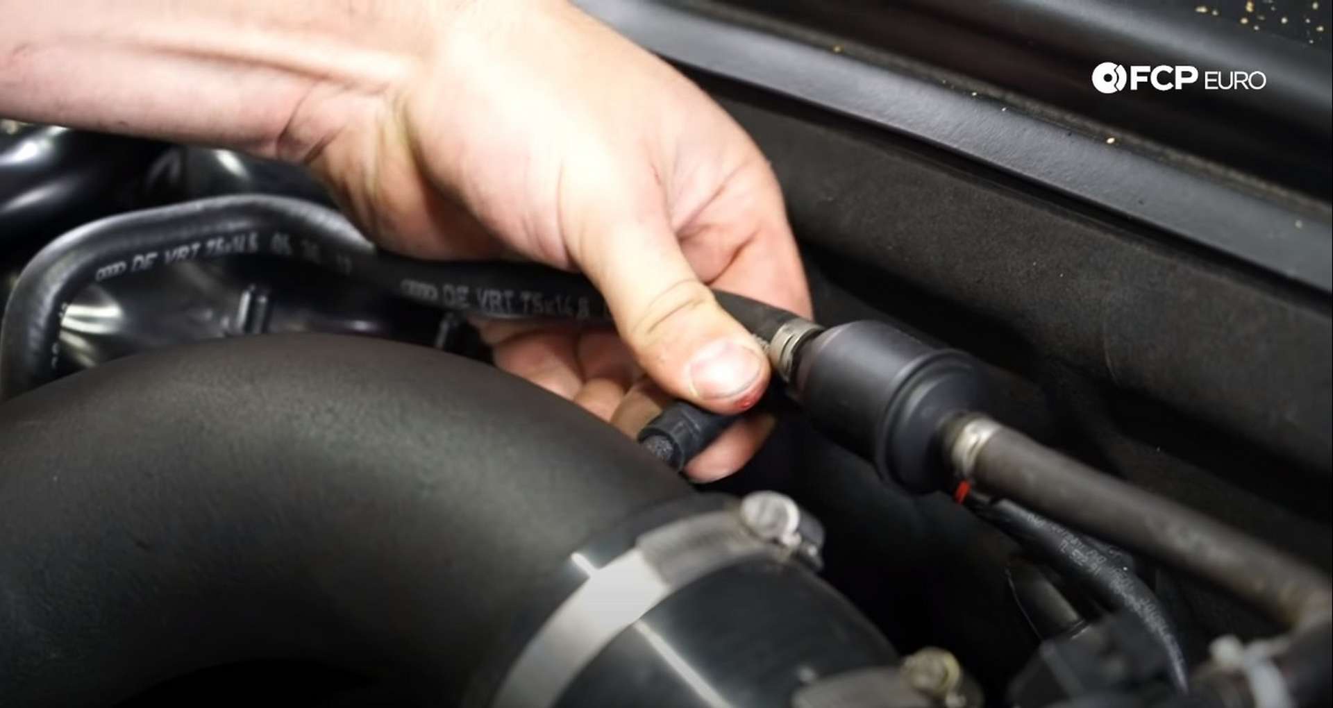
Torque the supercharger nuts to 20Nm. Next, attach the coolant hoses to the front of the supercharger and clamp them down. Then, use a T30 Torx socket to install the bolt that secures the coolant lines to the engine.
![DIY Audi 3.0T PCV/AOS Replacement reconnecting the coolant hoses]](https://images.contentstack.io/v3/assets/blta5fd5c563cb3dbc3/blt52bdcef240131f97/65cb4e7f2fbb390db05fbc7f/51-DIY-Audi-S4-PCV-Replacement_Supercharger-Reinstall.jpg)
Next, reconnect the vacuum lines and three electrical connections on the back of the supercharger. Then, move to the other side of the engine and reattach the electrical connections by the throttle body.
After that, install the covers that sit under the MAP sensors on either side of the supercharger. Use a T25 Torx socket to tighten the bolts. Then, reconnect the MAP sensors on either side of the supercharger.
Next, reach down in front of the engine and pull up the supercharger belt. First, ensure that the belt is still correctly oriented on the engine's pulleys. Then, use a long 16mm wrench to release the tension from the belt tensioner. While holding the tensioner, use your other hand to reinstall the belt onto the supercharger.
Step 7: Refit the intake
Take the intake assembly and fit it into the engine bay. Attach the intake tube to the throttle body, then seat the airbox into place. Clamp the airbox down and use an 8mm socket to tighten the intake hose clamps.
Lastly, attach the vacuum line to the intake.
Step 8: Fill the coolant and test the engine
Open the expansion tank and fill it with coolant. Then, open up the bleeder screws on the supercharger. Start the car and run it, allowing the air to bleed from the cooling system. Keep an eye on the coolant level and add it as you see fit.
As the engine runs, check for any coolant or fuel leaks. If everything checks out, jack up the front of the car and reinstall the undertray. Slide the front of the tray into the bumper and lock the tray into place with a T25 Torx socket or screwdriver.
Audi PCV Replacement Torque Specs:
- Audi Supercharger Nuts = 20Nm or 15 ft-lbs of torque
- Audi Intake Manifold Hardware = 9Nm or 6.6 ft-lbs of torque
- Audi Fuel Line Connections = 27Nm or 20 ft-lbs of torque
- Audi Fuel Pressure Sensor = 22Nm or 16.2 ft-lbs of torque
- Audi Intake Manifold Threaded Fuel Line Fitting = 40Nm or 29.5 ft-lbs of torque
- Audi PCV/AOS Bolts = 9Nm or 6.6 ft-lbs of torque
Just like that, your PCV system is back to full health. If you're interested in more DIYs for your Audi, you can visit audi.fcpeuro.com or subscribe to our YouTube channel. If you have any questions or comments, leave them in the comments below.