Over several articles last month entitled “Chill Out” I discussed light restoration and conversion from R12 to R134 refrigerant for on a 1975 Mercedes 450SL.
In this article however, we will discuss the removal and installation process of the Mercedes 450SL A6 compressor for either repair work or restoration.
NOTE: This job is not particularly easy and may require a few unexpected tools.
The first process in removing the A6 compressor is to remove the fan, fan shroud, radiator, and charcoal filter for the fuel vapor recovery system and properly vacuuming down the A/C system. Future articles will be done covering the removal of specific components from the Mercedes 450SL engine.
Once all the necessary components have been removed, it is now time to remove the compressor. Begin by disconnecting the upper refrigerant hoses from the two main lines that connect to the back of the compressor.
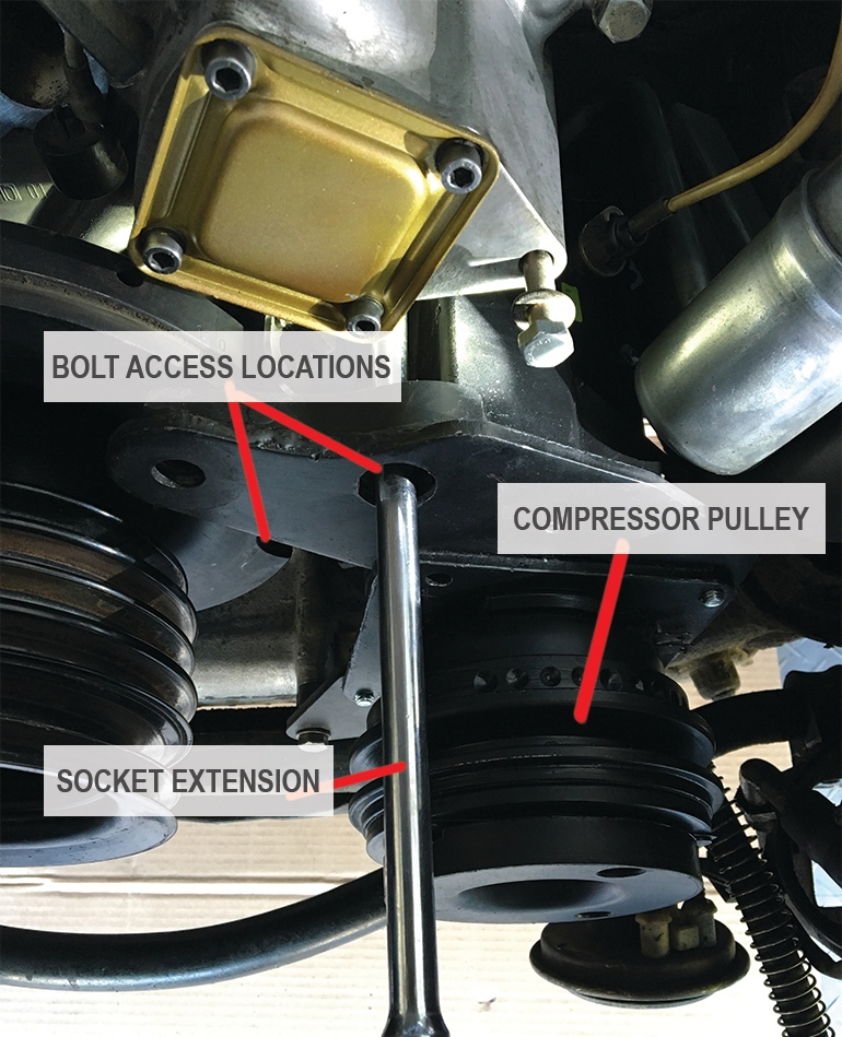
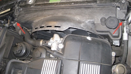
Next loosen the two socket screws on the left side of the compressor bracket. These two socket screws also serve as two of the many fasteners that retain the timing chain cover. These two bolts will be accessed by way of a port located in the compressor bracket as shown and through one of two notches formed in the vibration damper. The vibration damper must be turned clockwise by hand using a socket and breaker bar and must align with the bolt to insert socket.
It will also be necessary to remove the TDC (Top Dead Center) sensor from the bracket in order to get the socket and extension to the bolt directly through the compressor bracket port. To do this an 8mm socket with extension must be used as shown. Once the 8mm nut and washer has been removed it is now possible to gently pull the plastic sensor from the bracket. Installation is the revers. Do Not over tighten this nut.
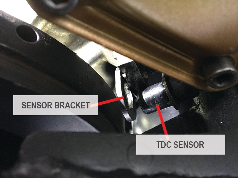
Photo shows TDC sensor
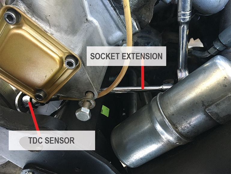
This photo shows socket wrench and extension in place to remove TCD sensor
IMPORTANT: If you have not personally done this project before, you must be sure that there is no dirt/grease filling the “keyhole” of the screw before inserting your hex key. You DO NOT want to strip the head out of this bolt! If one or both of the socket screws is stripped and you can not get a allen key inserted to remove it, you are pretty much left with one option in this case — use an air hammer and a great deal of patience. You will be working in two areas that have near zero line of site.
Removing a stripped socket screw from a Mercedes
Should you be the recipient of one of these stripped socket screw(s) as I was, here is the method of removal. With an air hammer and chisel attached, drive a notch or slot in the center of the screw. Go through the head far enough to create a deep slot as in a flat head screw. Once the slot has been created, re-angle your air hammer so the chisel is at about a 45o angle downward with the force toward the left side of the screw to begin the loosening process. Pulse the hammer to begin the bolt turning out. At this point you should be able to use a drill with the chisel end or large screwdriver to remove the screw. Your access and maneuverability is extremely tight. Also, if you have left your A/C condenser in place, be careful not to crush the fins as you are working.
The chisel will be placed through the following “openings” for the removal of either or both bolts. These are the same “openings” that would be used to remove and install the bolts as normal.
Now that we have sufficiently loosened our potentially stripped out bolts, we can continue to loosen the remaining hex bolt and proceed to the back of the compressor.
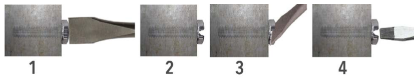
Image shows steps in removing a bolt with an air hammer
To access the final two bolts at the rear of the compressor, you will need to have the front end of the car on ramps or jack stands. I have made wooden “cribs” that a friend of mine turned me on to and they work incredibly well. I also like this because they are wide enough and strong enough to place wheel turn tables to assist in working on steering and front end components.
NOTE: When replacing these two bolts, I chose to replace the two socket screws with standard hex screws (bolts) for ease of removal and installation for the next time. In addition, one bolt was already trash to start with. I decided to change them out because they could not be seen at all when viewing the engine. I was told by a tech., one of the reasons Mercedes and or other manufactures use socket screws in various locations, is to alert the mechanic that they have gotten to a bolt or set of bolts that are securing more than one major component. In this case, you could easily begin removing these bolts and because you are unable to see them, not know they are securing the A/C compressor.
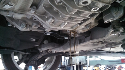
Once the front bolts have been loosened, the two rear bolts will now be removed. The photo below shows the location of the bolts securing the rear of the compressor.

Photo shows rear compressor bracket bolts
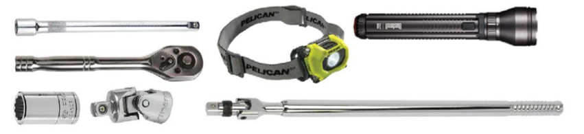
To remove these bolts it will require a 13mm socket, an extension and U-joint. The space to work with is very awkward and quite tight. In addition, to make this job easier it is very helpful to have an LED head light as you will need to get light into this black hole. If you do not have a head light, you can angle and rest a very bright flashlight from above that will offer some, but not great assistance.
Now remove the front bolts. Again, do not remove the main lines from the compressor at this point, they will come out with the compressor upon removal. When removing the last front bolts, the compressor will be able to rest on the subframe and not fall through.
When the bolts have been completely removed, and the compressor is sitting on the subframe, it is ready to be pulled from the engine bay. The compressor is very heavy and must be lifted and rooted front to back while lifting to avoid damaging the condenser fins. The compressor weighs roughly 40lbs.
With that, you are done and install is the reverse. Take lots of pictures of the process as you disassemble the compressor bracket so you remember how everything was set up! It’s worth the few extra minutes of your time on every job.
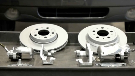
Possible parts needed:
- A6 Compressor or Pulley and Clutch assembly
- Compressor Belt- Belt Tensioner
- PAG 150 Compressor Oil
- O-rings
- Hoses
- Schrader Valves and Caps
Helpful tools you hope not to need:
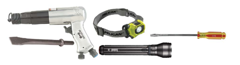
Helpful tools: