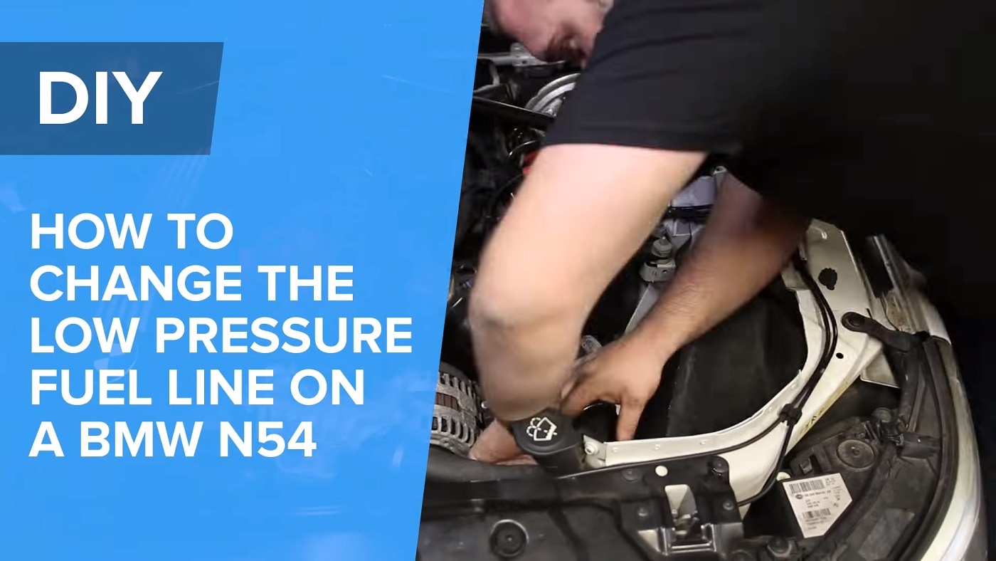
Spoiler alert, this job isn't that hard to complete. Cure that pesky 29F3 code.
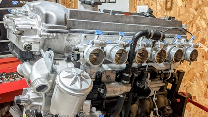
The N54 fuel system is composed of two separate but equally important systems. There is the low pressure side (from the in-tank fuel pump to the high-pressure pump) and then the high-pressure side (high-pressure pump to the direct fuel injectors). Both the low-pressure and high-pressure systems use sensors to monitor pressure in both systems. A fault on the low-pressure side can cause an array of performance issues and incorrect pressure on the high-pressure side can also cause performance issues.
The low-pressure sensor located just before the inlet of the high pressure pump is a common issue and mostly fails in two ways:
- A constant pressure and volt reading at all engine loads or fuel pump speeds
- No voltage or pressure reading
BMW changed the design of the low-pressure fuel sensor and in doing so now have an updated low-pressure line. It is important to verify which pressure sensor your BMW has as in my opinion it's worth updating to the newer design. If updating to the newer design you will need to order the line (which includes the pressure sensor). If you already have the updated line all you will need is to order the updated sensor. You can still get the older style sensor but in my opinion it's a better idea to get the updated sensor as it's less failure prone.
Video: For a full tutorial on the process, click the video below and don't forget to subscribe.
Tools needed to complete this repair:
- Flat head screw drivers
- 1/4" quick disconnect tool
- 17mm line wrench or open ended box wrench
- Silicone spray
- Metric socket set
- 13537622751 - Low Pressure Fuel line with Sensor (if updated to new sensor and have original line)
- 13537622231 - Updated Low Pressure Fuel Sensor (if you already have the updated line)
- 13537614317 - Original Low Pressure Fuel Sensor (if you want to keep original line)
Step 1: I highly recommend disconnecting the negative battery cable first since you'll be working on a fuel line near the starter motor. The clamp for the battery cable is tightened with a 10mm nut.
Step 2: Remove the cowl cover. This will vary by vehicle but overall this wil require basic hand tools. The reason for doing this is to gain access to the rear diverter valve.
Step 3: Remove the air box cover by releasing the metal clips. I use a 90-degree pick to do this but a flat head screw driver will work too. Also, release the vaccum line by depressing the tabs on the quick disconnect. This will most likely be stubborn to remove but take your time as it can break easily. Once these two items are out of the way you can remove the bottom part of the airbox by loosening the hose clamps. Once the clamps are loose lift up on the lower housing. It's held in with rubber grommets so it should com out easily.
Step 4: You will now remove the diverter valves on both of the air intake pipes as well as the charge pipe leading to the throttle body. They are secured in place with a twist lock. Simply rotate the twist lock 90 degrees counter clockwise and lift the diverter valve out. Also remove the vacuum lines for the diverter valves. I recommend taking a small plier and twist the vacuum line gently on the nipple to "break" the seal and aid in removal.
Step 5: You will now remove the charge pipe from the inercooler to the throttle body. Onthe throttle body end lift up on a the clip using a pick or flat head screw driver. It will fall into its "open" position once it's fully released. On the intercooler side release tension on the hose clamp. Once both ends have been loosened remove the charge pipe from the intercooler first and then release the charge pipe from the throttle body.
Step 6 (Optional): Remove the throttle body by first removing the (4) 10mm bolts that secure it to the intake manifold. Once it it loose flip it over and remove the vacuum line (it has a quik release similar to that next to the air box) and disconnect the electrical connector. You can now remove the throttle body which will give you better access to the electrical box affixed to a bracket on the intake manifold.
Step 7: Remove the electrical box on the bracket connected to the intake manifold. This is affixed via tabs and it can be a challenge to release. I recommend using a little bit of silicone spray to help aid in removal You will also need two thin flat head screw drivers to depress the metal tabs under the plastic hooks. Once it starts to slide off it will come off easily.
Step 8: At this point you can now see the low pressure fuel line and the high pressure pump. You will see a lead that goes from the electrical connector housing to the low pressure fuel sensor. Disconnect the electrical connector for the low pressure fuel sensor at the housing as is easier to do it this way vs disconnecting at the connector. I use a small pick to depress the tab and it should come unplugged easily.
Step 8: Now you will begin removal of the low pressure fuel line. I recomend loosening the flare nut at the high pressure pump first. Do not remove completely at first but loosen this nut to release pressure from the low pressure fuel line first. Have a rag in hand to reduce any fuel spray. Also wear eye protection. Once fuel is completely done spraying unthread the flare nut and separate the line from the high pressure pump. At this point you will have more room to release the quick disconnect between the hard line and the flex line. Insert a 1/4 quick disconnect tool and press in until the quick disconnect releases. I recommend capping off both the high pressure pump inlet and low pressure line if you have caps that fit to prevent foreign material from getting into the fuel system.
Step 9: Swap the low pressure sensor harness from the original sensor to the new sensor. Begin installation on the quick disconnect side first by pressing the hard line into the soft line. The quick disconnect will snap into place. Next thread the 17mm flare nut into the high pressure pump inlet. Make sure it's tight (bottomed out) on the high pressure pump inlet. Connect the other end of the low pressure fuel sensor harness into the electrical junction. I recommend plugging the battery back in and turning accessory mode on. This will prime the in tank pump. You will be able to see if there is a fuel leak before putting all the other parts back together. Now you're ready to reassemble in reverse order.
Quick tips on reassembly: If you removed the throttle body for access make sure you replace the throttle body gasket. When reinstalling the diverter valves twist the quick releases into the locked position before installing the diverter valves. This will allow for the valves to "click" into place without addidional effort as the locks can be tight to turn. To aid in reasembly of the charge pipe I recommend using a small amount of silicone spray on the rubber boot to allow for charge pipe connector hose to slip into place easily.
Key torque specs for reassembly:
- Throttle body to intake manifold - 8Nm
- Low pressure line to high pressure pump - 30 ± 3 Nm (add a little but on transmission oil to threads)
- Low pressure line bracket to engine block - Replace aluminum screw, 10Nm, Torsion angle adjustment 90° ± 15°
Step 10: Reassemble all other components keeping in mind the quick tips above. Start the engine and verify that the new low pressure fuel line is providing correct readings. Clear out fault codes and run the car. It may take a long crank to start but don't worry as the system needs to build pressure again. Run the car and check for fault codes.


