- 09/10/2020
- 23 Min Read
- By: Christian Schaefer
How To Replace The BMW N20 Timing Chain (Part 2 - Reassembly)
An engine's timing belt or timing chain keeps all of the components of the engine in the right place at the right time. A belt or chain skipping a tooth can cause the valves to hit the pistons, destroying the engine. Timing chain systems, while safer than belts, are far more difficult to service. When it comes to the BMW N20 timing chain, this means expensive and lengthy services to prevent a ruined engine.
Replacing the BMW N20 timing chain and guides is not for the faint of heart. This job requires several specialty tools and a wealth of wrenching experience. With that said, it is a doable job for a DIY'er if enough precaution is taken. You run the risk of severely hurting the engine if any of the steps are not done correctly, but if you follow along with our DIY, you'll have the entire process laid out step-by-step.
BMW N20 Timing Chain Replacement Part 1
BMW models and years applicable:
|
|
|
|
|
|
|
|
Symptoms of a failing BMW N20 timing chain:
- A rattling or clacking noise coming from the front of the engine on start-up
- Listen to the noise at 0:44 in the video
A timing chain will stretch over time. As it stretches, the chain gains play, allowing it to move around inside the timing cover. If a chain stretches enough, it can come loose on one of the sprockets causing it to jump off, or the sprocket will move more than the chain does. Engines are built to tight tolerances, and a worn chain puts the internal parts outside of those tolerances.
If the chain hasn't stretched, then something has happened to the guides. The timing chain guides, as their name suggests, keep the chain on its proper path at the proper tension. The guides are made from plastic. Improper oil maintenance, excessive heat, or even a faulty design from the manufacturer can cause the guides to wear quickly or crack.
If you were not aware, there was a BMW N20 timing chain recall because this issue was so prevalent. The recall isn't only for the faulty timing chain guides, but also for the timing chain itself stretching. Some models with the N20 were recalled while others fall under an extended warranty.
How much will it cost to service the timing chain system on the BMW N20/N26?
The job itself requires three special tools specific to this engine. Factoring in the cost of the tools with the parts brings the DIY bill to nearly $1200. The cost will get higher if you have to buy any of the other tools needed for the job.
However, if you were to go to a dealership for this job, out of the 7 year/70,000 mile warranty, you'll be on the hook for more than that. The labor alone will be between 10-15 hours, causing the cost of the job to be upwards of $5000.
For those capable or bold enough to take on this job, there is a lot of monetary savings to be had.
How long will it take to service the timing chain system on my BMW N20/N26?
Set aside at least two days to give yourself ample time to do everything correctly and double-check your work. There are a lot of small pieces that need to be removed and unclipped before getting into the heart of the timing system. Missing something during reassembly will only cost more time and headaches.
The dealer will charge you between 10-15 hours to complete the job. Depending on the parts in stock and who is available to do the job, they could have the car upwards of a week.
Tools required to service the timing chain system on the BMW N20/N26:
- 2x Floor Jacks
- Jack Stands
- 10mm Wrench
- 13mm Wrench
- 14mm Wrench
- 17mm Wrench
- 8mm Socket
- 10mm Socket
- 16mm Socket
- 22mm Socket
- 24mm Socket
- 27mm Socket
- E6 Socket
- E7 Socket
- E8 Socket
- E10 Socket
- E12 Socket
- E20 Socket
- T30 Socket
- T40 Socket
- T45 Socket
- T60 Socket
- 8mm Hex Socket
- 5mm Hex Socket
- Pick
- Flat-head Screwdriver
- Torque Wrench
- Pry Bar
- BMW N20 N26 Timing Tool Kit - CTA 7675
- BMW Flex Plate Lock Tool - CTA 2801
- BMW N20 N26 Balance Shaft Seal Tool Kit - CTA 7676
Parts required to service the timing chain system on the BMW N20/N26:
Steps for reassembling the BMW N20/N26 timing chain assembly:
Step 1: Assemble the new timing chain assembly
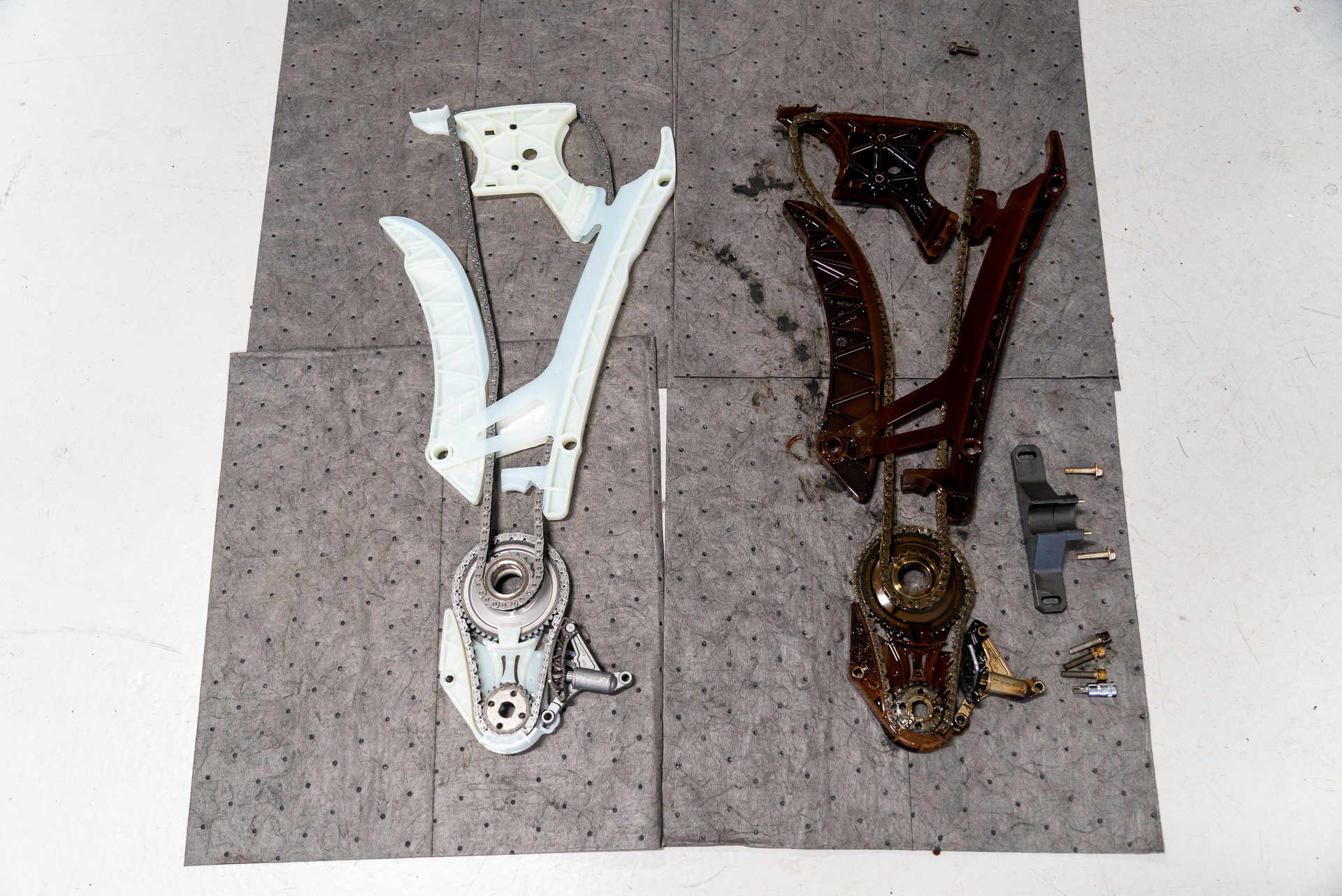
The new timing chain assembly is shipped unassembled and needs to be snapped together before being installed. First, take the chain, the three guide pieces, and the sprocket, and lay them out on a flat surface. Use the old assembly as a guide. The biggest guide goes on the right side of the chain, while the other long piece goes on the left side of the chain. The guide with the two bolt holes in the center goes inside the chain at the top, and the sprocket sits in the chain at the bottom. The image below shows how they should be laid out.
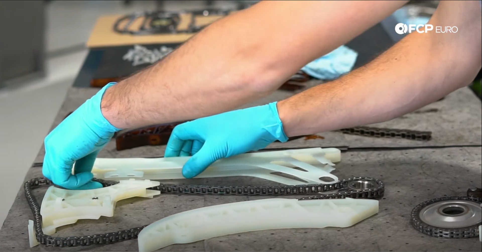
Slip the chain into the right-side guide, prying open the bottom just enough to get the chain inside. The right and left side guides get attached near the bottom of each other. Take the left-side guide and rotate it to the left so that the bottom is closer to the right-side guide than the top. Then, spread the ears at the bottom of the right side guide and slip the left-side guide inside of the ears. The circular cutout in the ears will line up with a circular raised portion on the other guide. Pinch them together and then rotate the left-side guide back to its vertical position to lock them together.
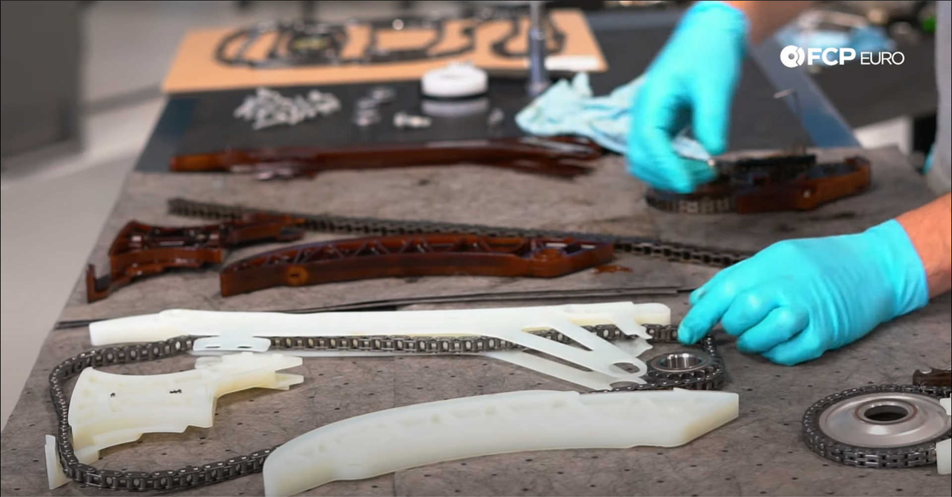
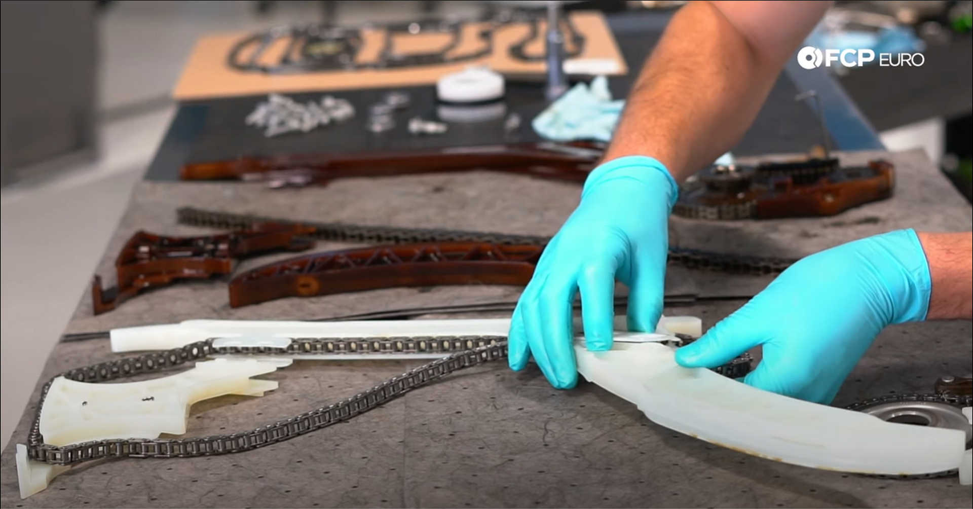
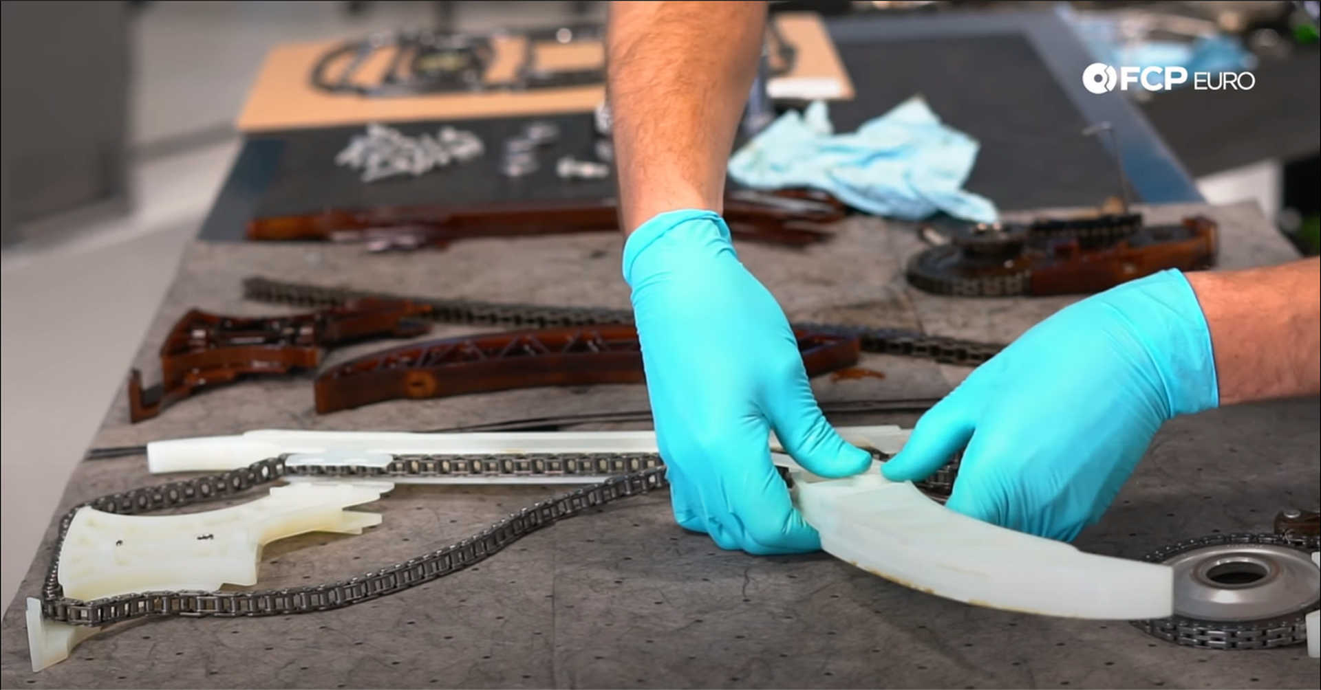
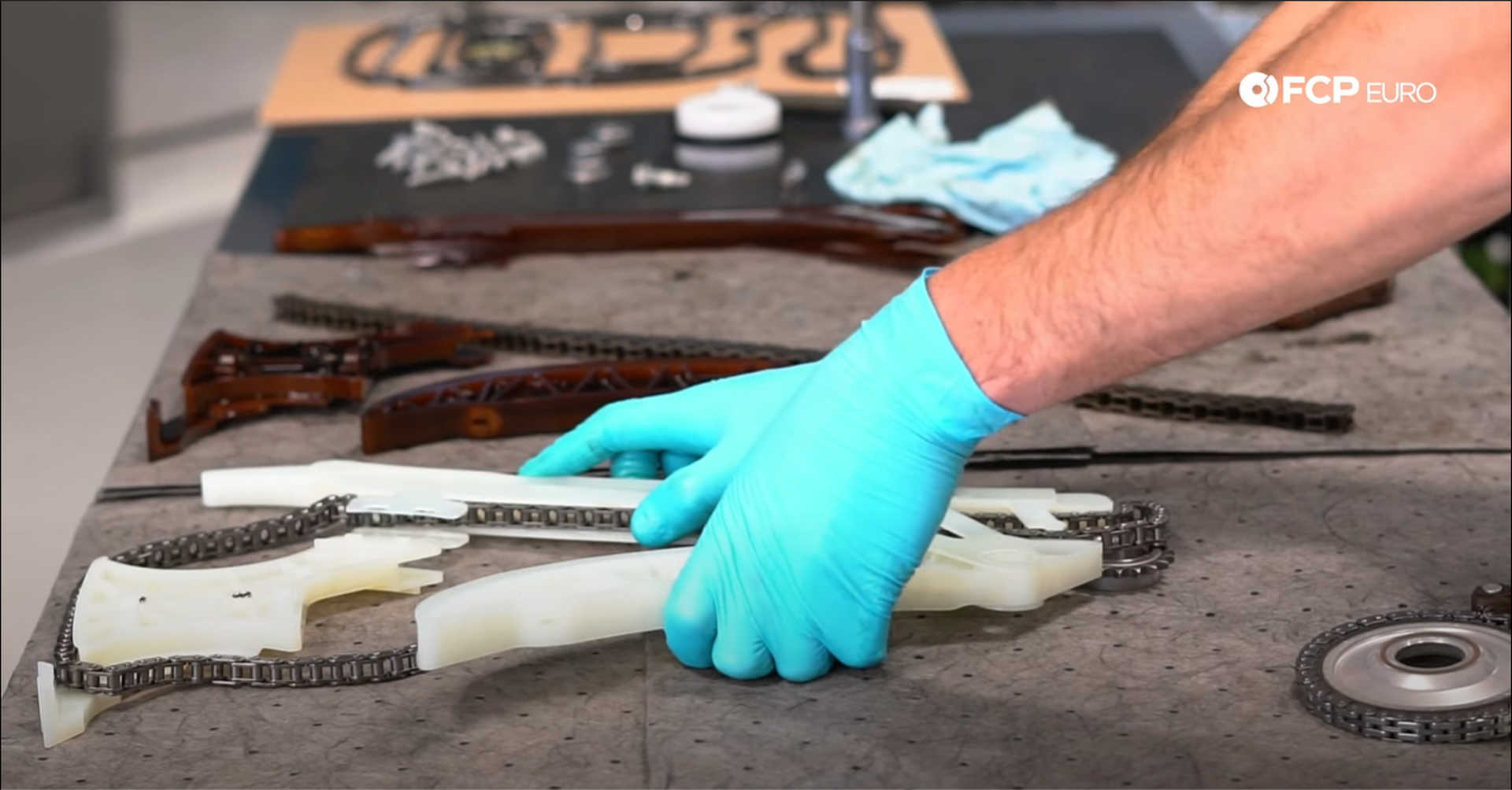
The top pair of ears on the right-side guide clip onto the upper center guide. Spread the ears open, fit them around the tabs on the center guide, and then pinch them to lock them in place.
Step 2: Install the oil pump drive assembly
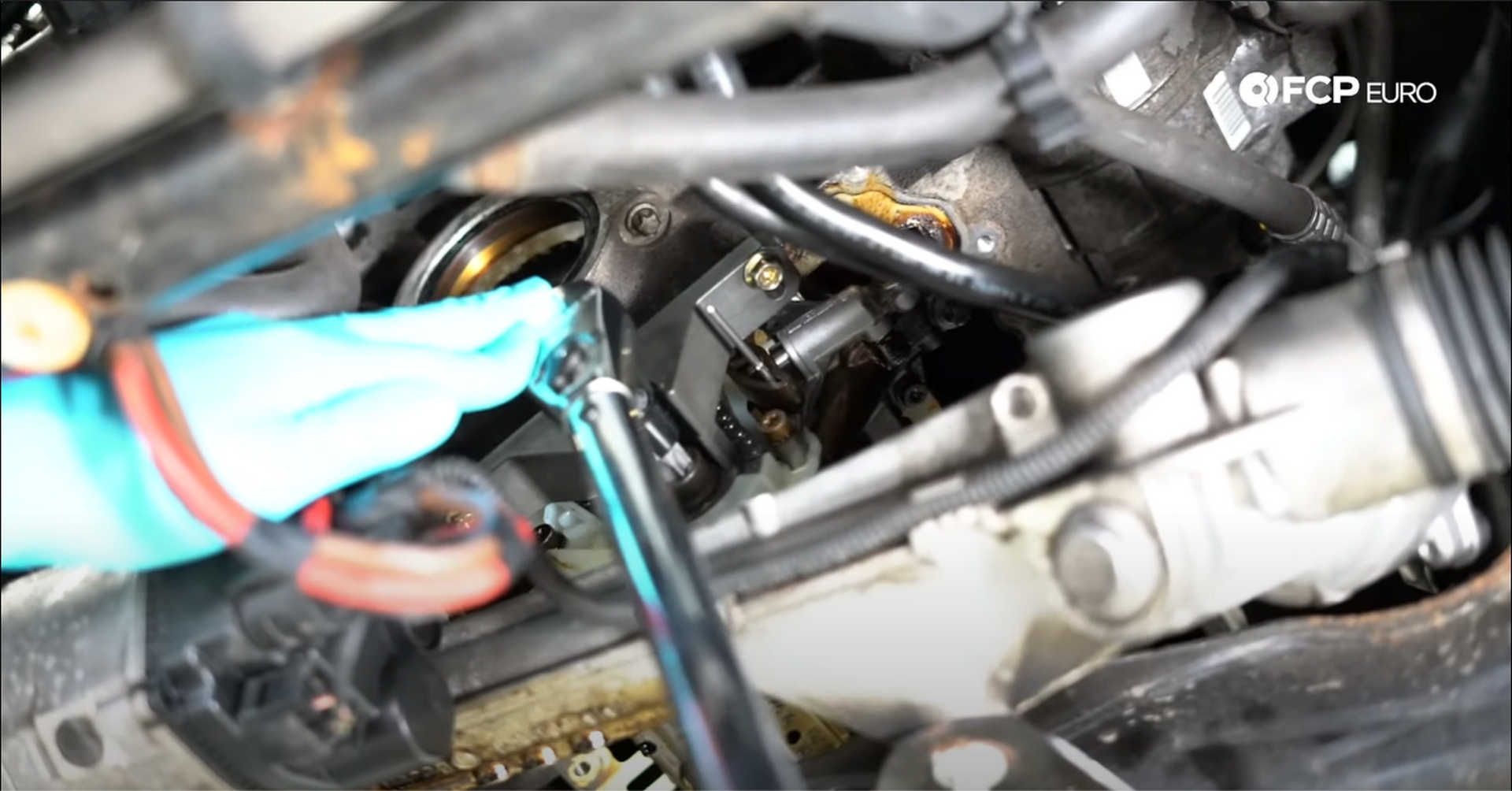
The oil pump drive assembly comes preassembled with the tensioner already locked in place. Feed the assembly up through the bottom on the engine and fit the balance shaft gear onto the balance shaft. The gear may need to rotate to align the flats on the shaft and inside the gear to slip onto the shaft.
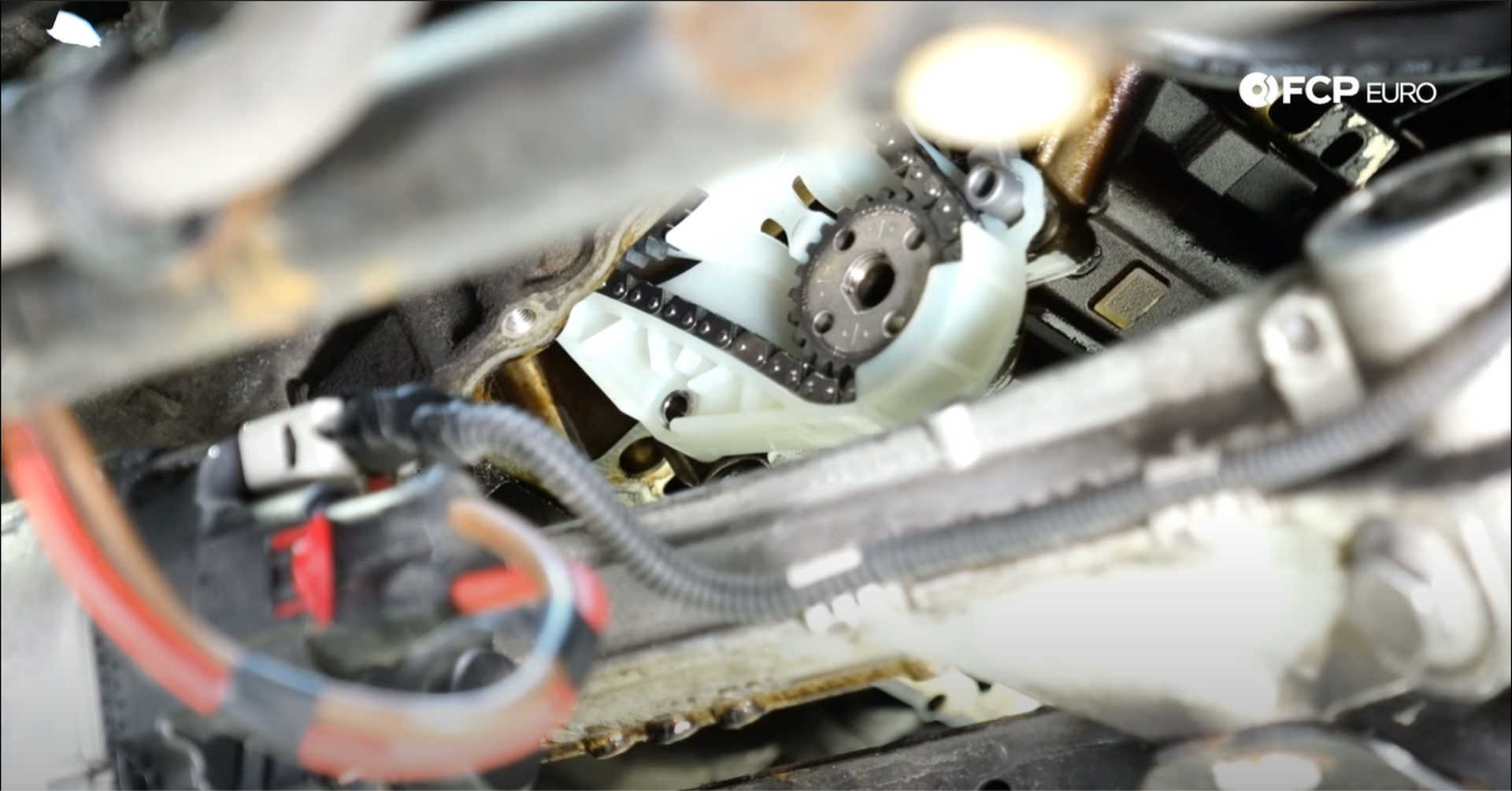
Once the gear is sitting on the shaft, thread in the three T30 bolts used to secure the assembly to the block. Thread them in by hand, so they don't become cross-threaded and tighten them to 10 N m with a T30 socket.
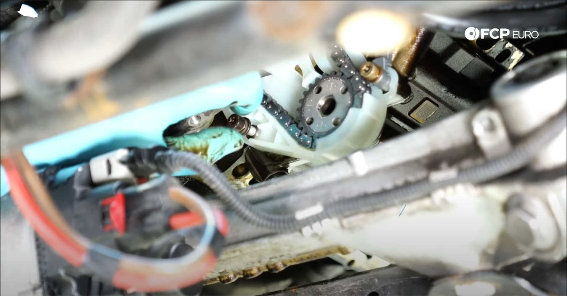
Next, install the CTA balance shaft locking tool used to lock down the sprocket. Tighten the tools mounting bolts with a 10mm wrench. Then thread in the new oil pump sprocket bolt by hand before tightening to 95 N m with a T60 socket.
Step 3: Replace the crankshaft seal
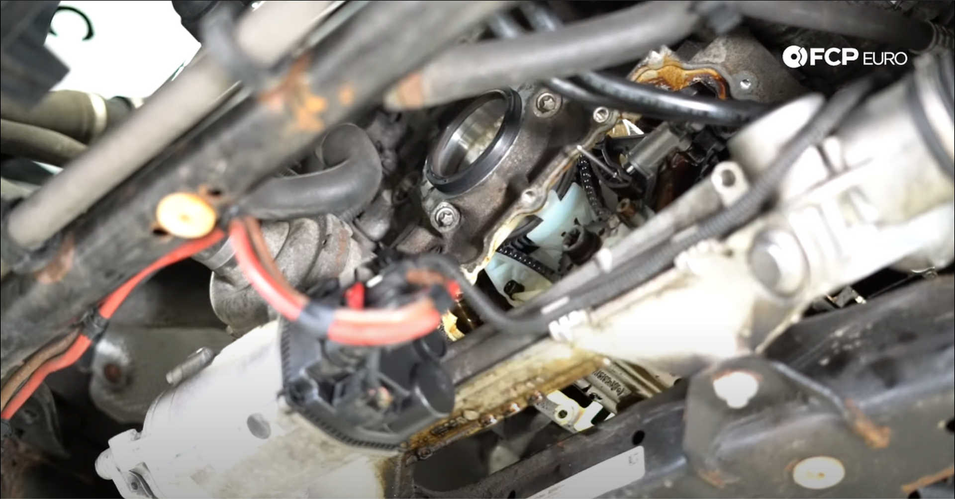
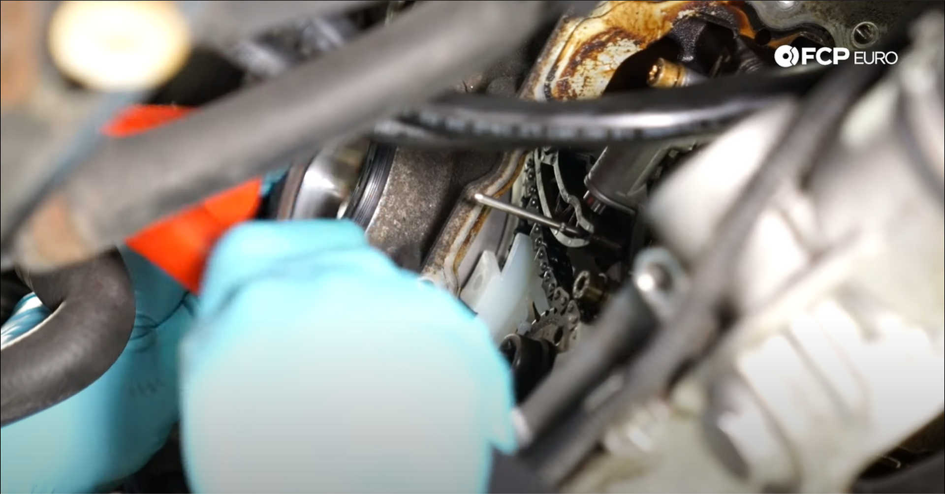
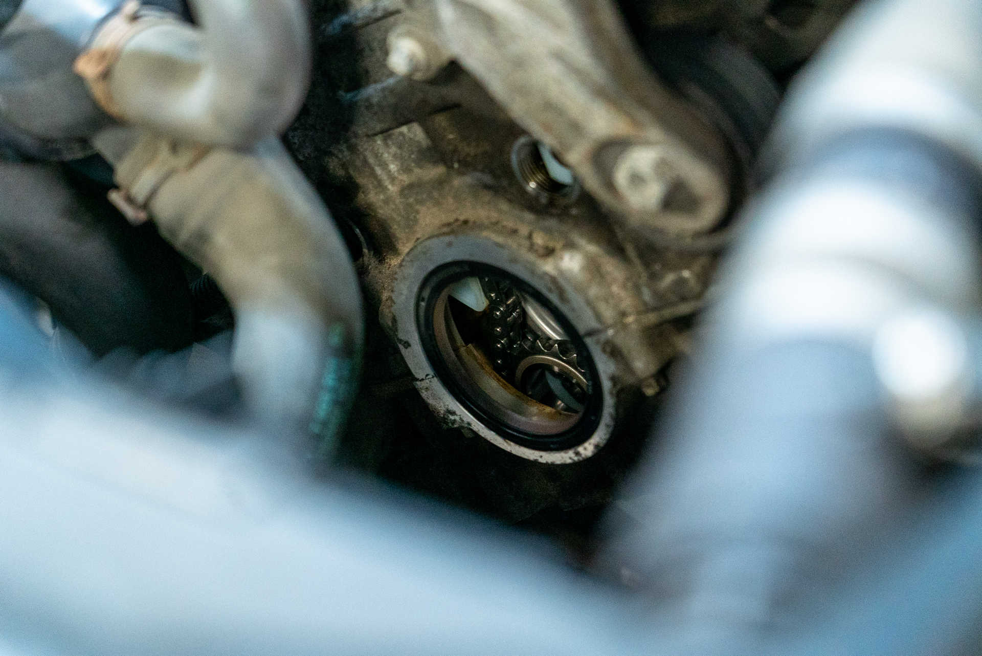
Use a hammer and chisel or punch to knock out the crankshaft seal. Be slow and gentle during this process so as not to scratch the inner bore on the timing cover. Line up the new seal in the bore and tap it into place with a plastic or rubber mallet.
Step 4: Install the timing chain assembly
Gather all of the tools and bolts you'll need to secure the guides to the car before anything else.
Then, pick up the timing chain assembly from the top and carefully drop it into the engine.
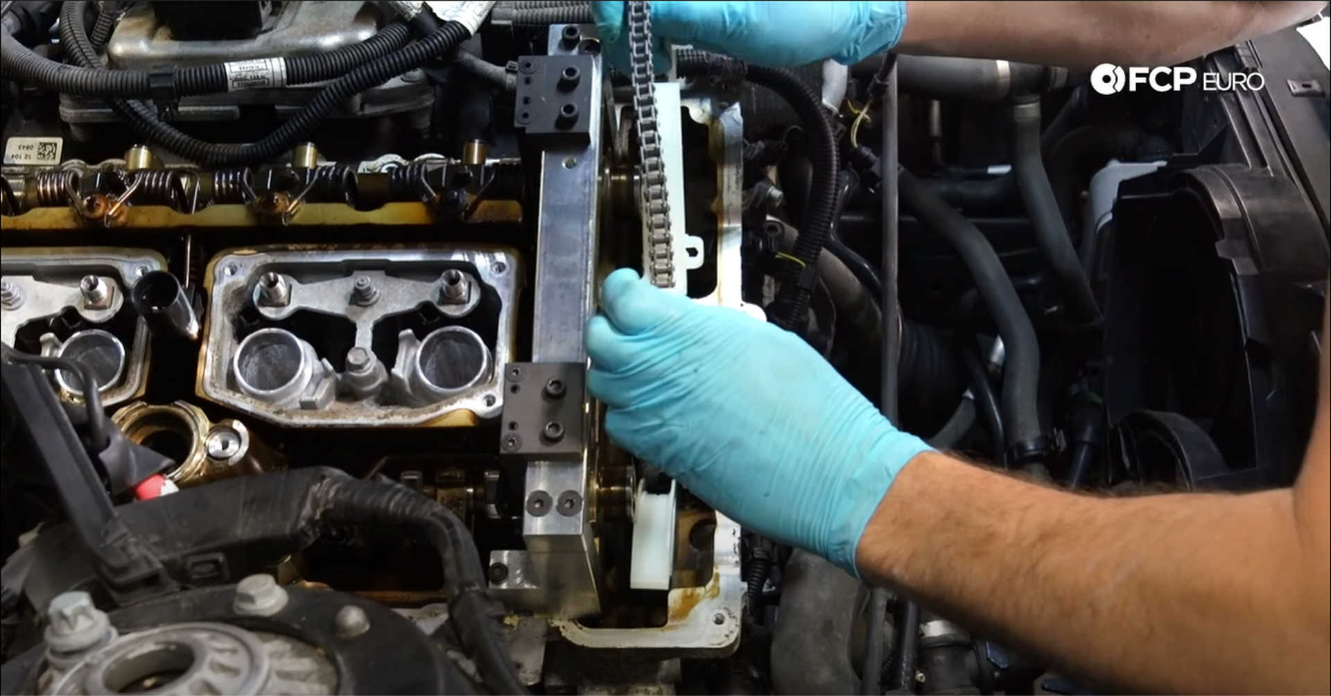
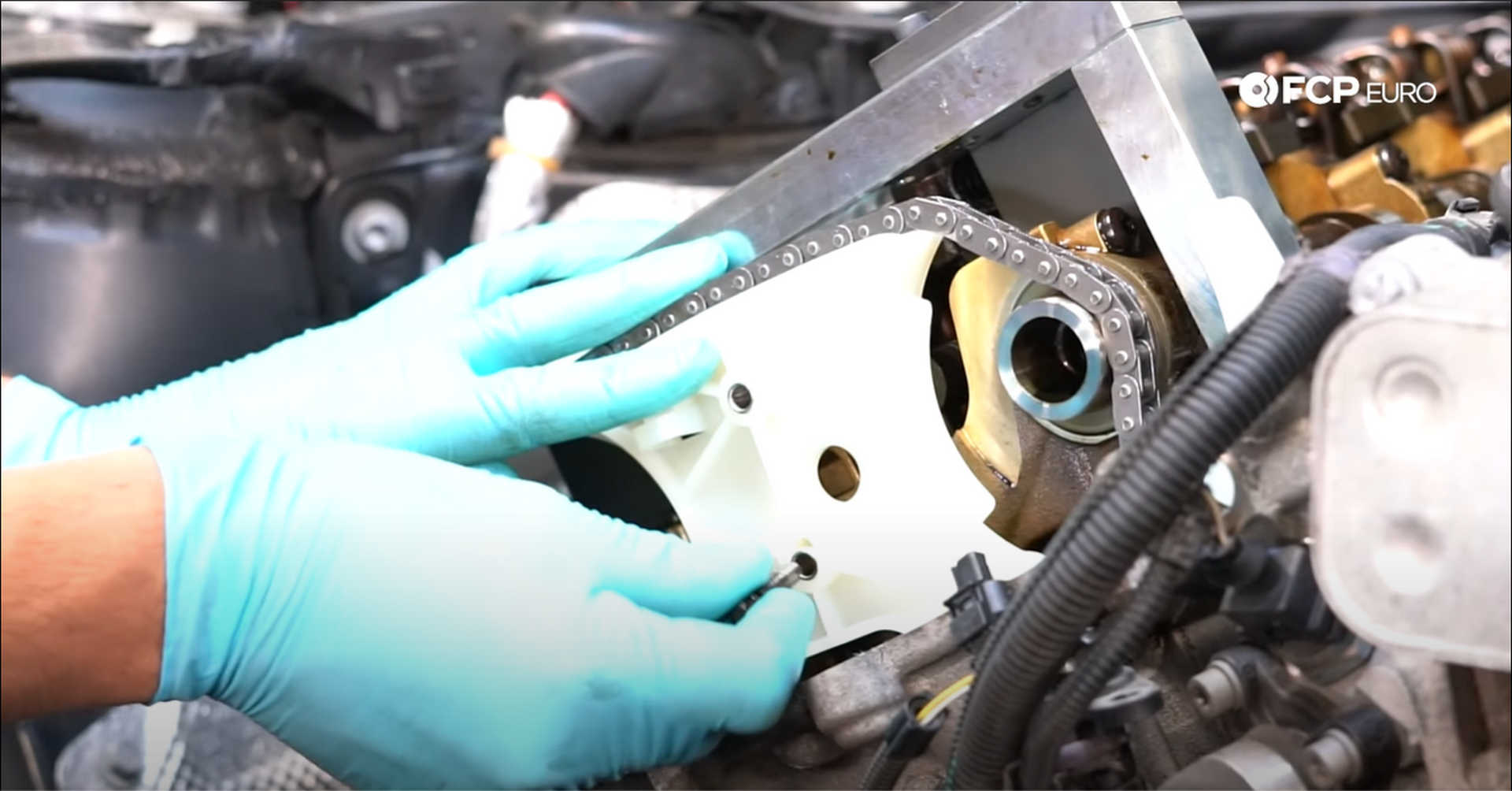
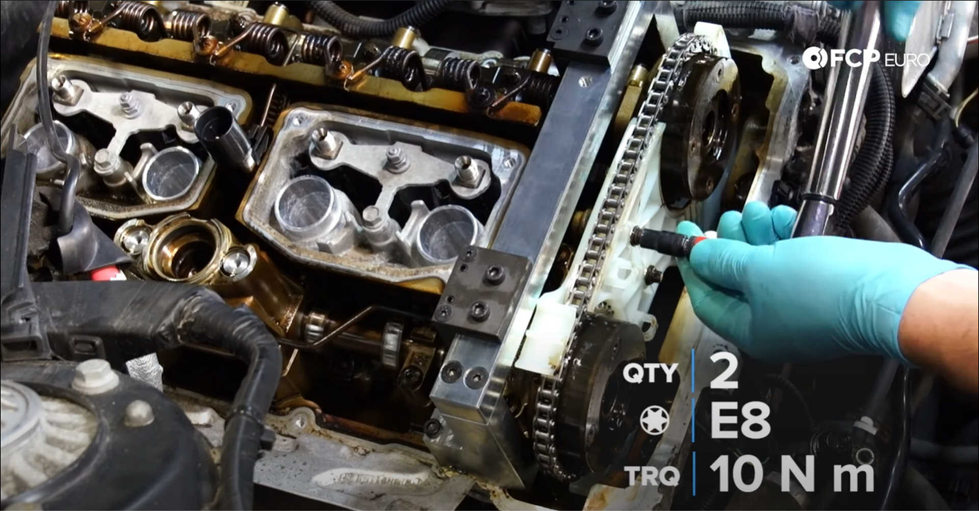
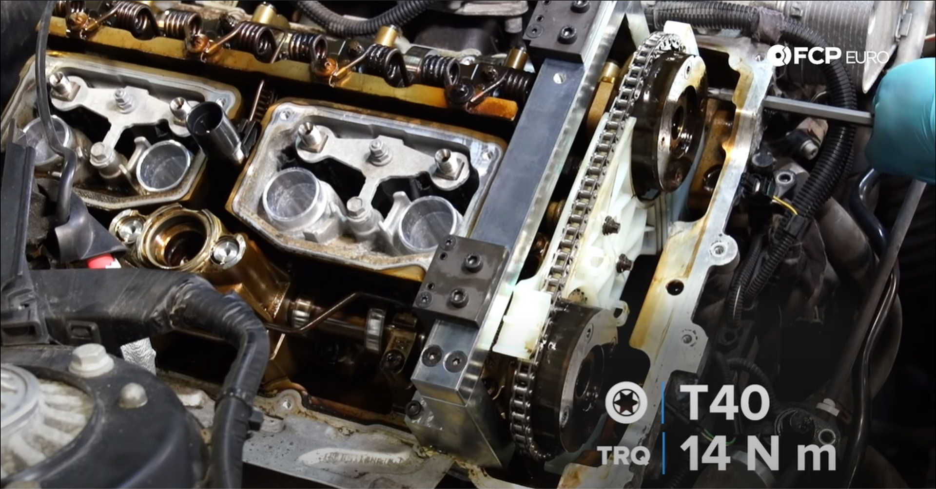
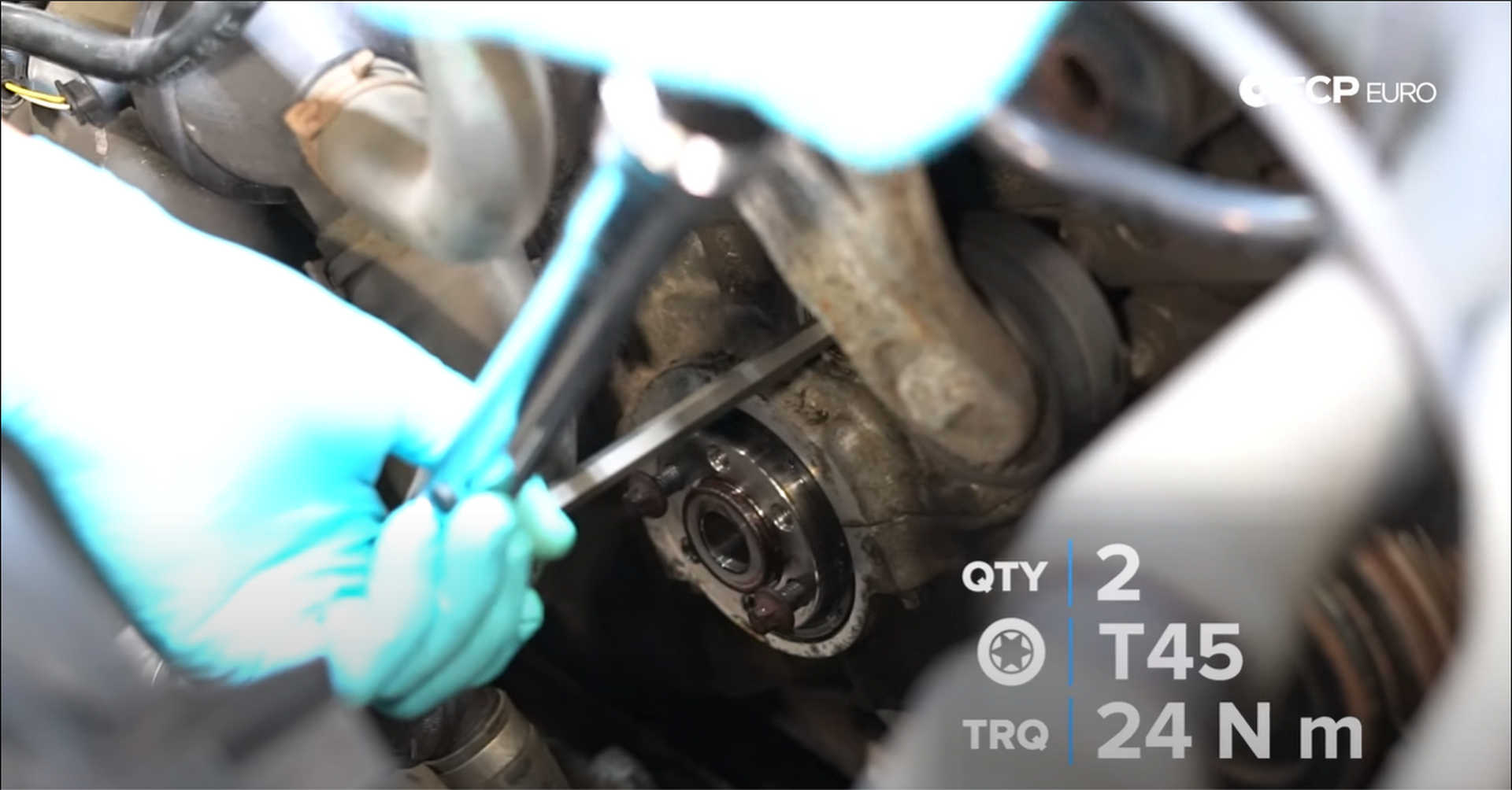
Once it is nearly in place, hold the assembly against the block with one hand, while threading in one of the center bolts with the other hand. Install the two E8 bolts first and then move to the T40 guide pin at the top of the right-side guide, followed by the two T45 guide pins just above the crankshaft. Only tighten the bolts and pins finger tight.
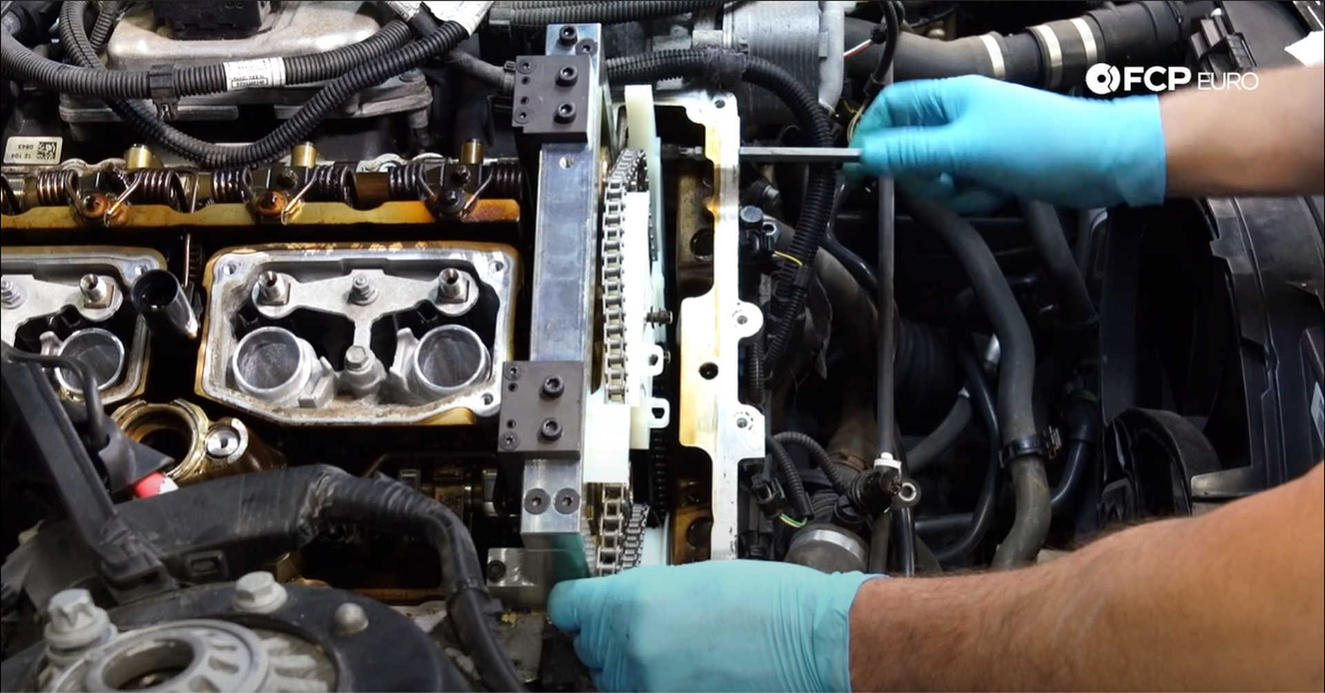
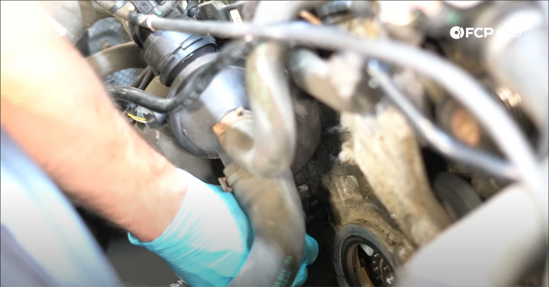
Make sure the bottom left guide pin goes through the chain guide and not behind it when installing. Thread it in a few turns, move the guide, and check to see whether or not it pivots on the pin.
Next, install the exhaust camshaft sprocket. Lift the chain and slide on the exhaust sprocket. Make sure the chain is seated properly in the teeth of the sprocket.
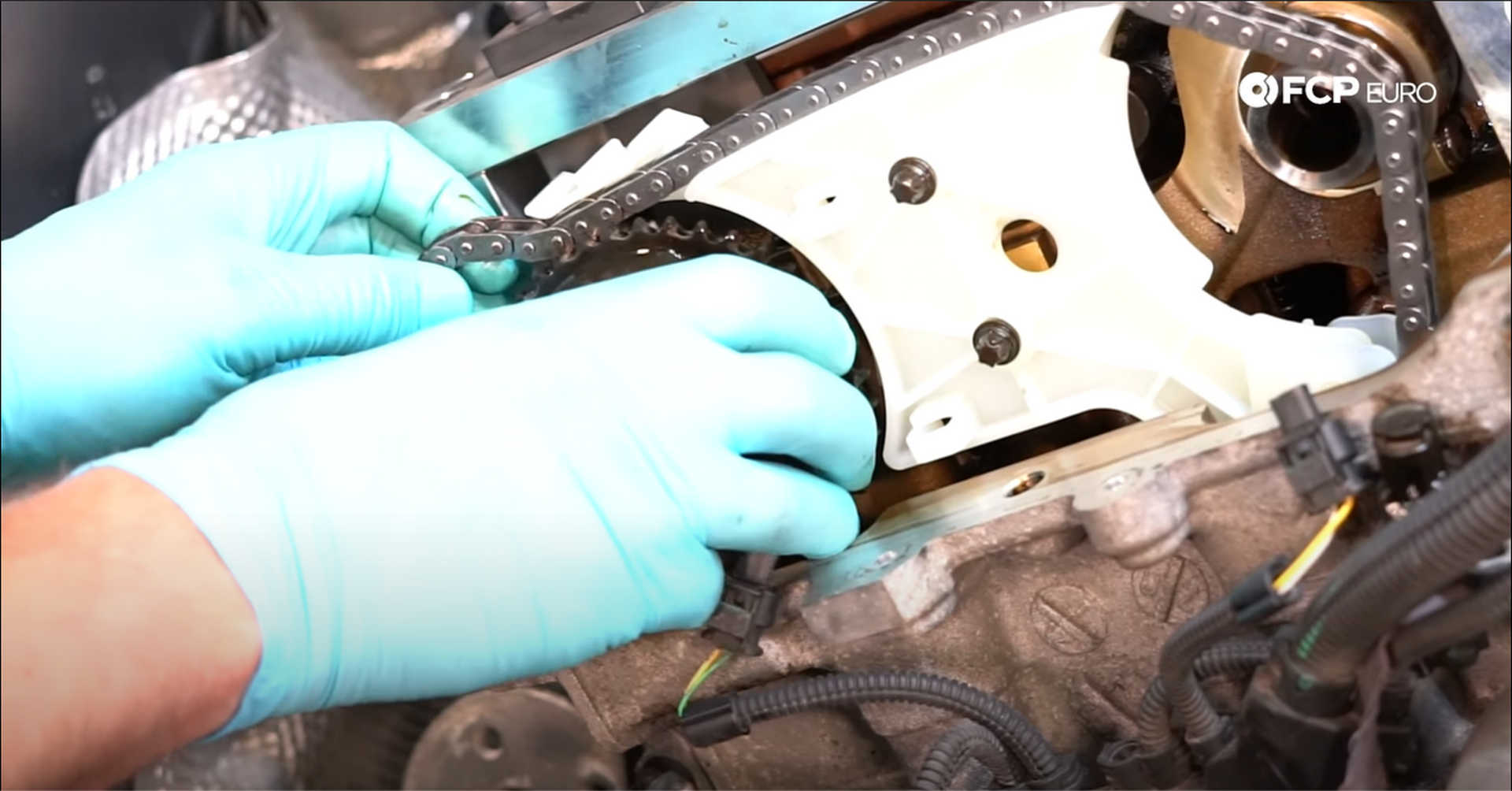
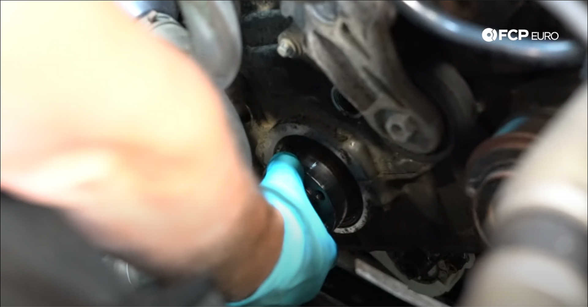
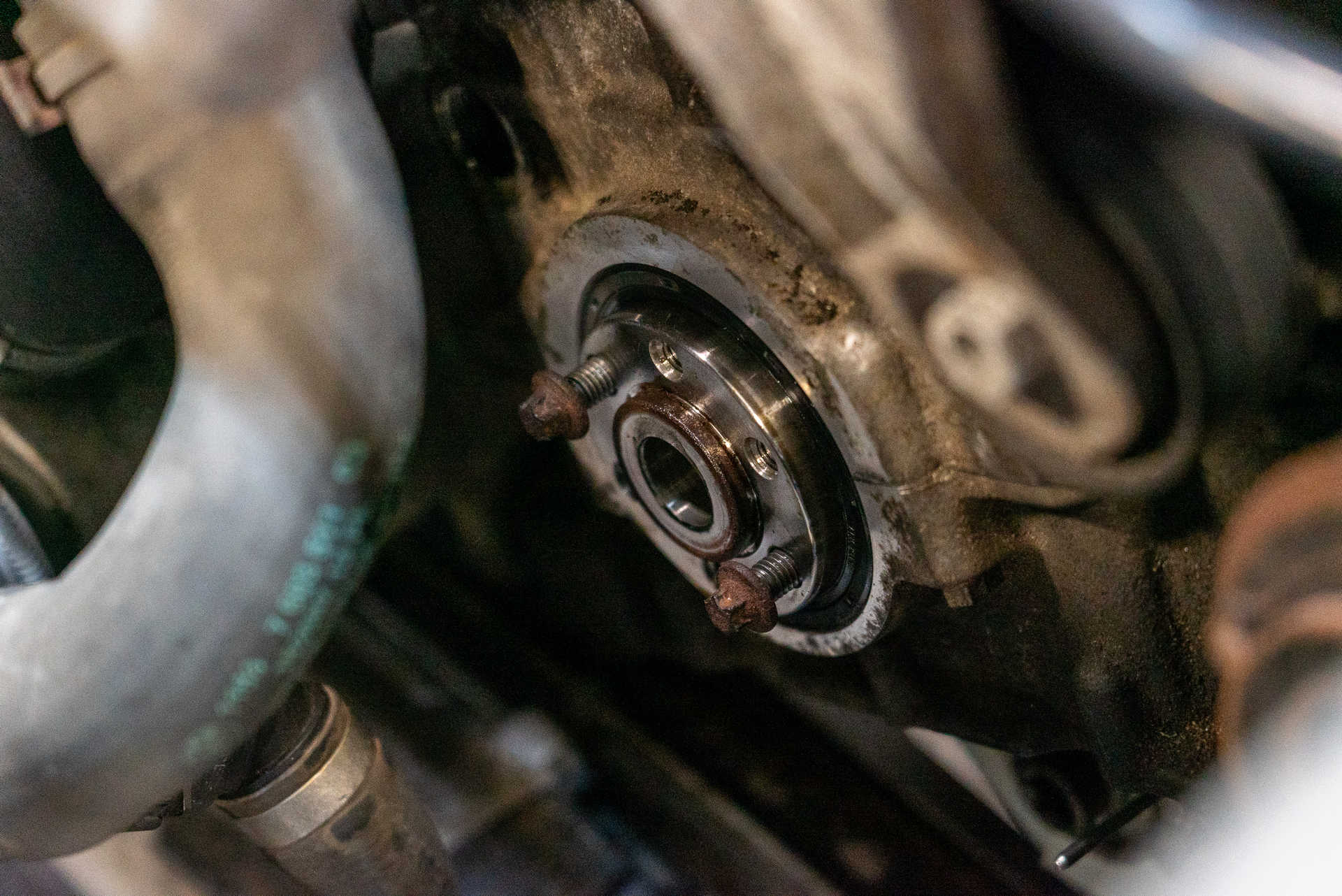
The exhaust cam sprocket is now taking up a large portion of the slack in the chain, allowing the vibration dampener mount to be installed onto the snout of the crankshaft. Start by lubricating the inside of the new crankshaft seal with oil. Then, using the two bolts used to remove it, slide and wiggle it into the front of the timing cover and through the small timing sprocket and the oil pump drive gear behind the timing sprocket.
The new timing chain won't have any play in its length, making the cam sprocket installation a bit tricky. Slide the intake cam sprocket onto the cam and work the chain onto the teeth. While sliding both of the sprockets on, you'll need to work the chain into the groove of the top guide as well.
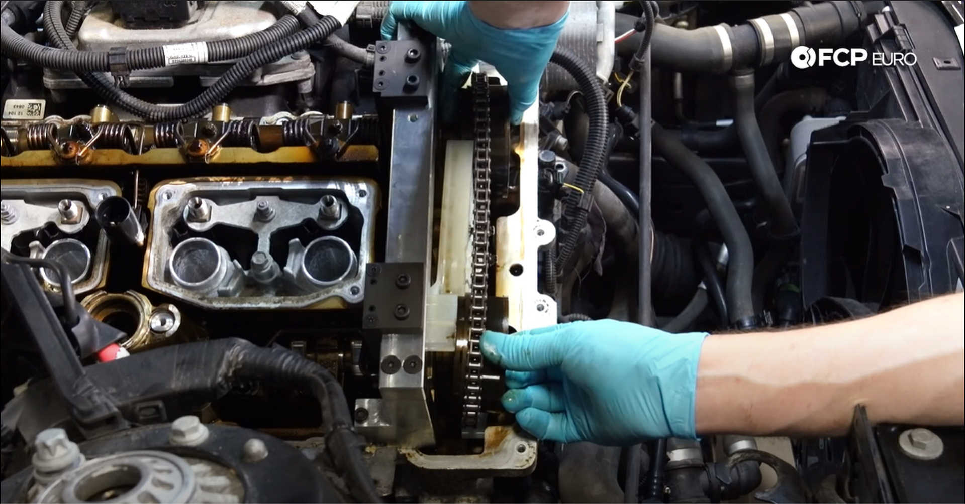
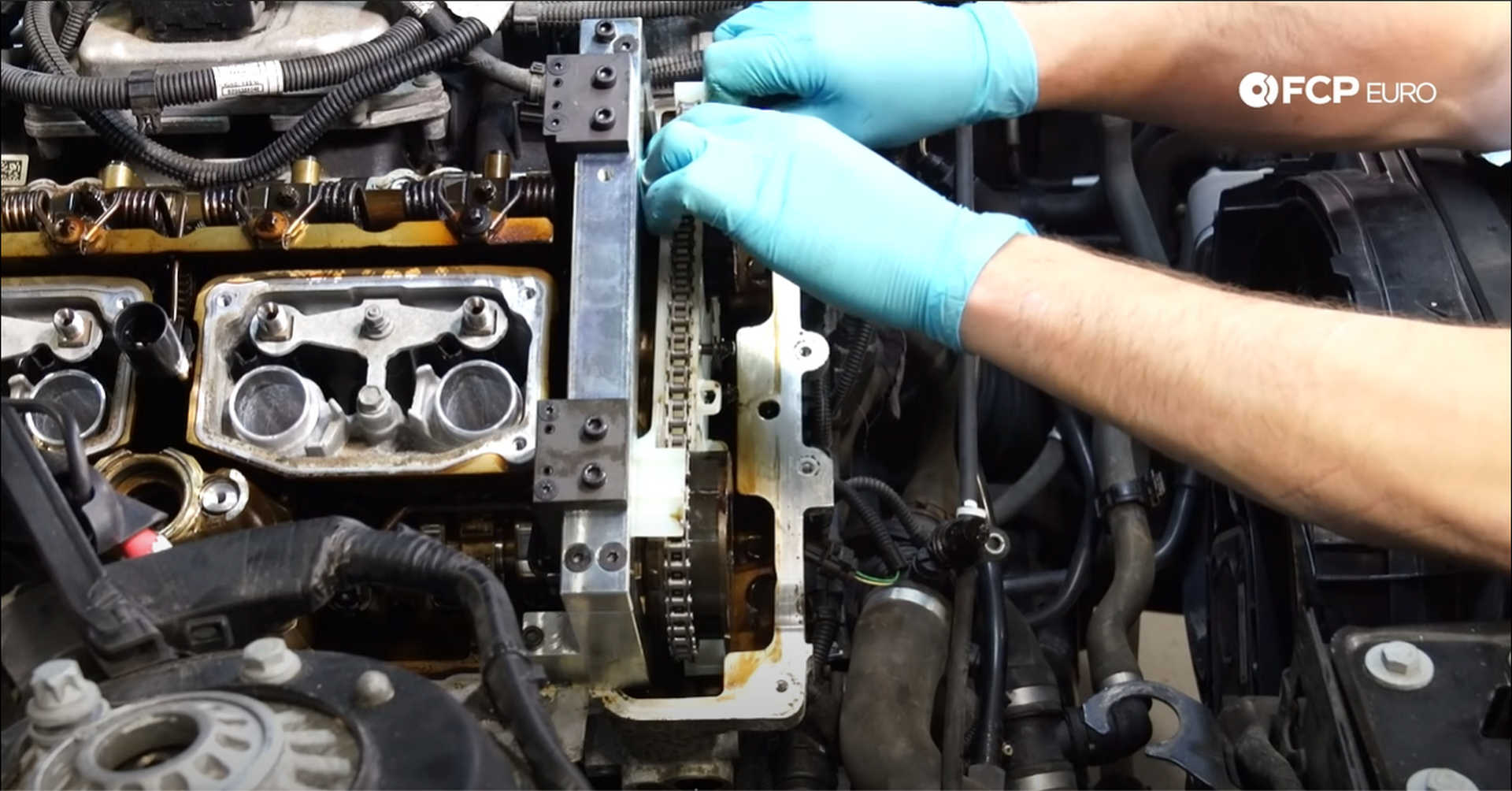
With everything in place, use a torque wrench to tighten everything to spec. The E8 bolt gets 10 N m, the T40 guide pin gets 14 N m, and the T45 guide pins get 24 N m of torque.
Step 5: Install the camshaft adjusters
Slide the cam adjusters into the cam sprocket and thread them on by hand. The adjusters are specific to the camshafts they sit on, so look for the I or E to determine which is which.
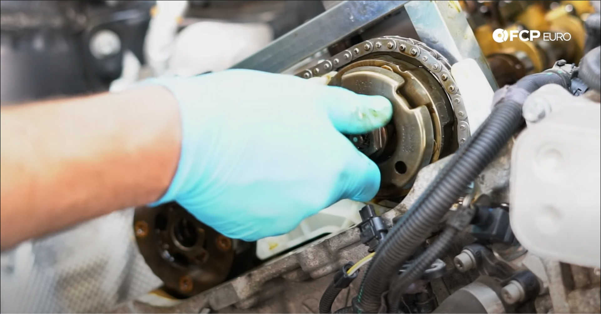
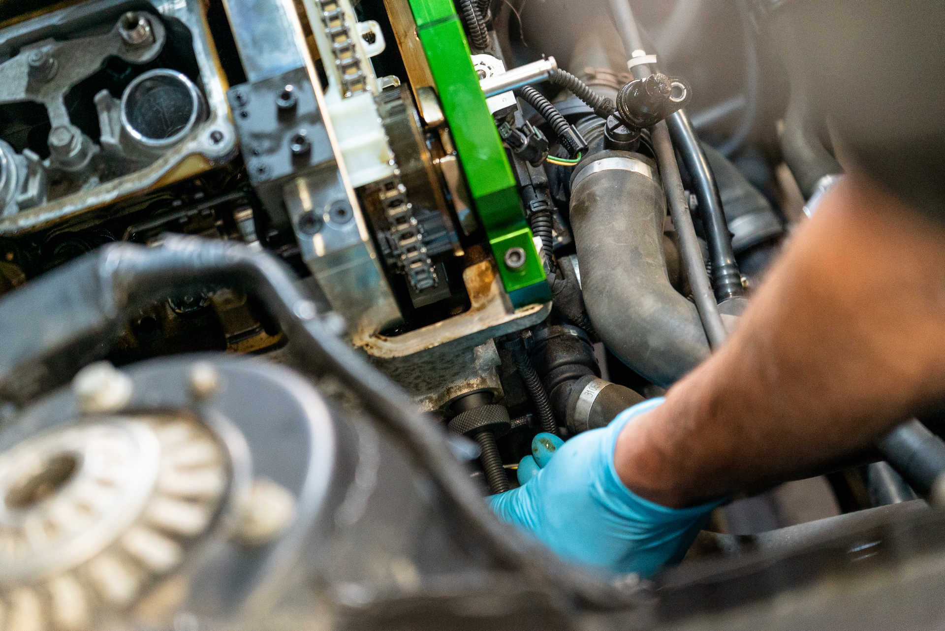
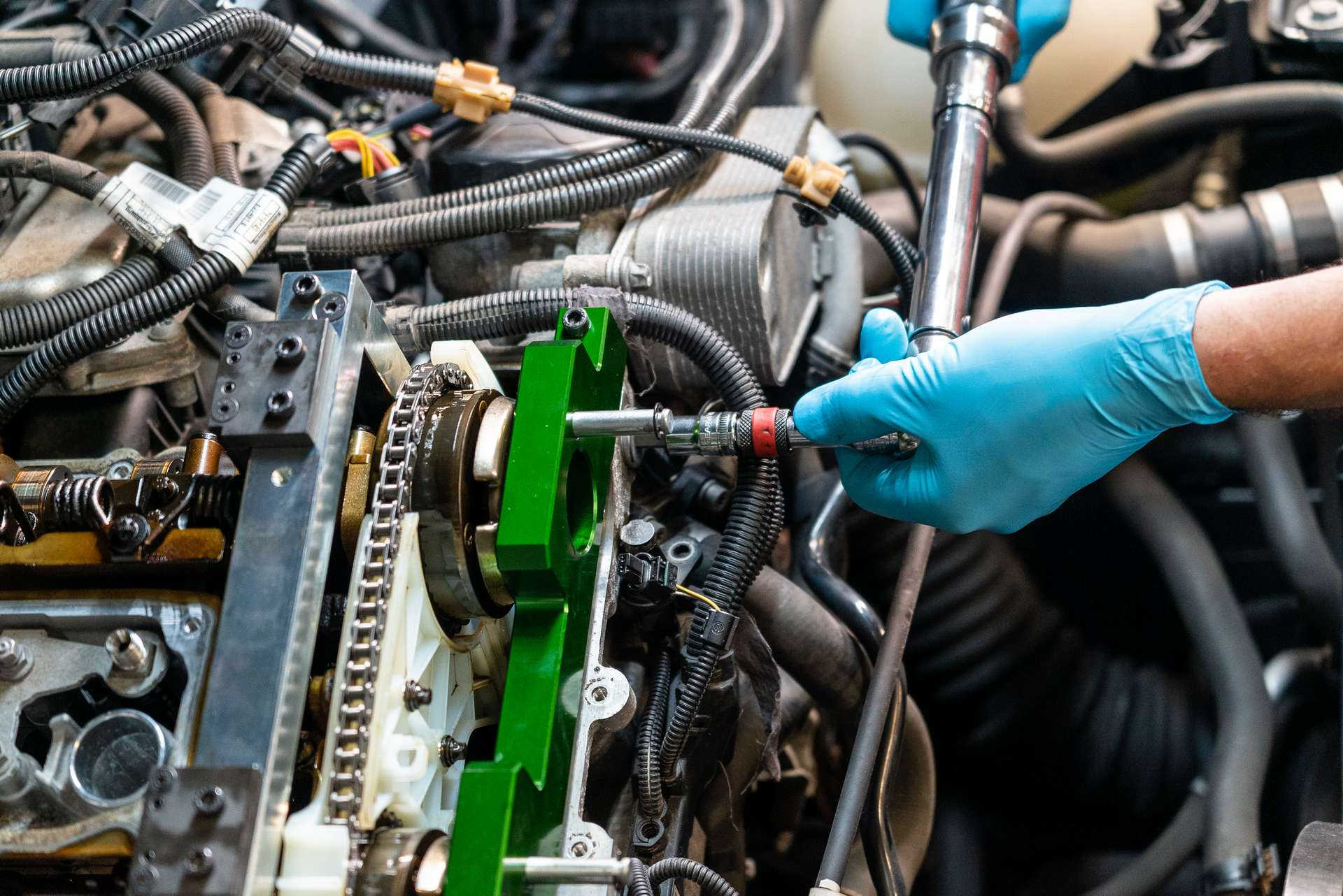
Next, grab the large green CTA timing tool and set it in front of the camshafts. Using the Allen bolts supplied in the tool kit, secure the cam timing tool to the front of the engine. Once it is secured, spin the camshaft adjusters until the holes in them line up with the pins in the timing tool. Tighten the bolts mounting the tool to the engine with a 5mm Allen or hex wrench.
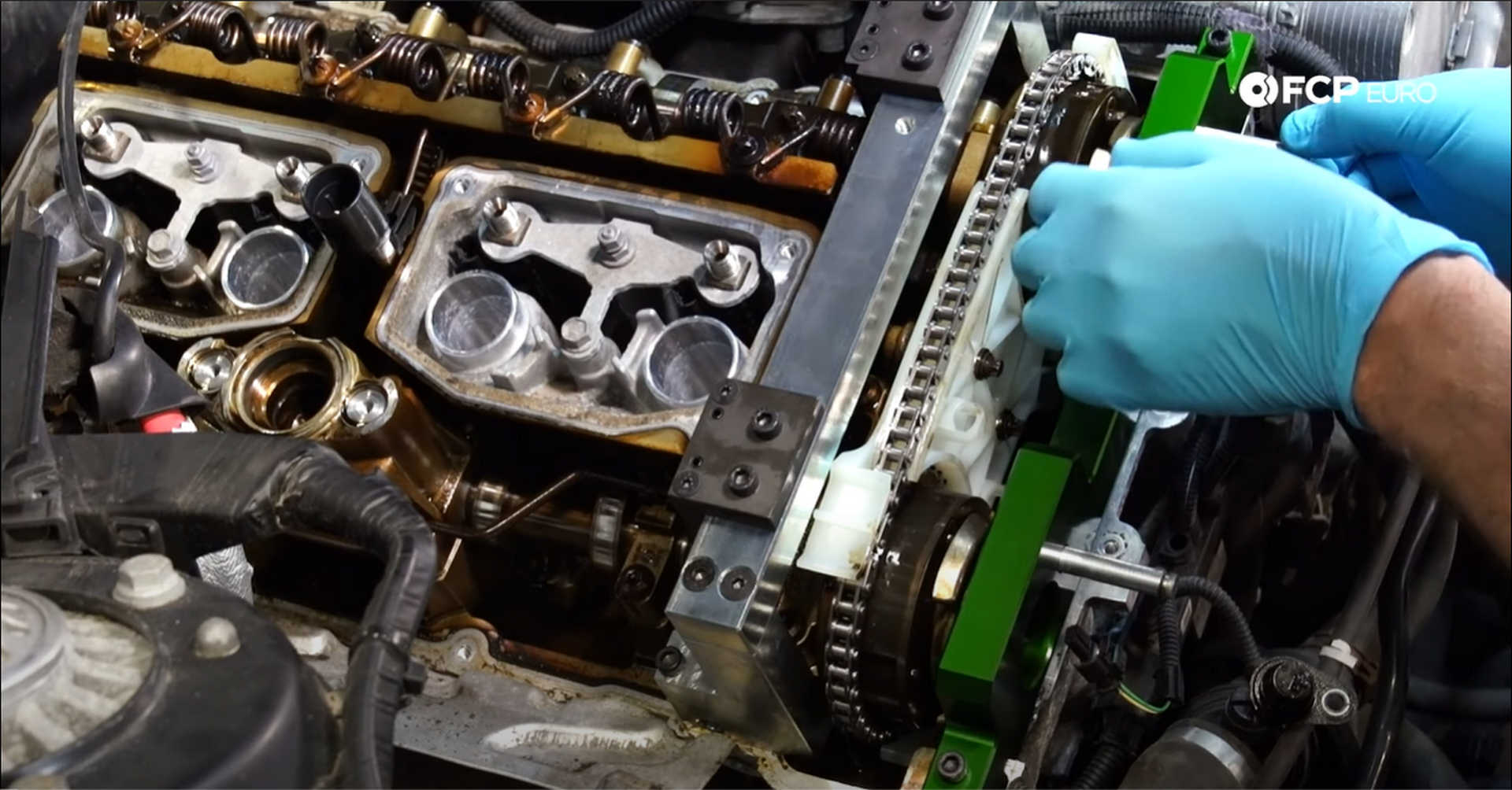
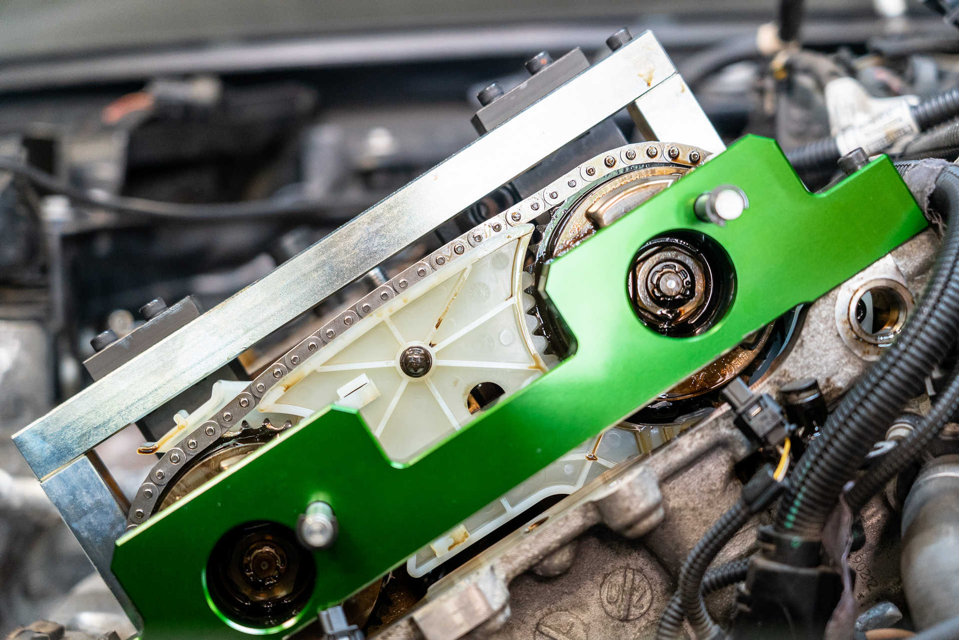
Use a 24mm socket to tighten the cam adjusters to 55 N m, plus another 55° of rotation.
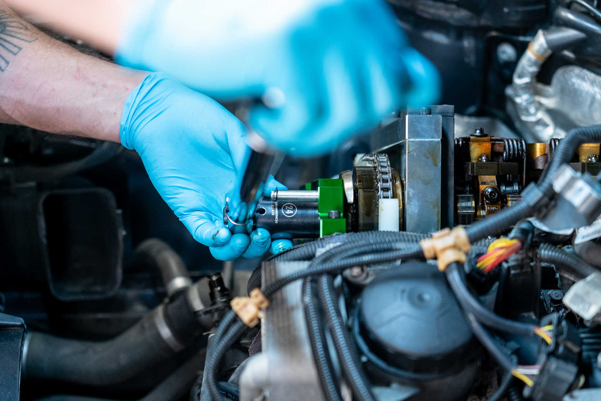
Step 6: Install the crankshaft bolt
Take the timing belt pre-tensioner and install it where the timing belt tensioner sits. Back the threaded rod out until the knurled portion of the tool sits against the block. Then, use an 8mm socket to tighten the rod to 0.6 N m or 5 in-lbs. If you don't have a torque wrench that goes that low, get the rod as tight as you can with your fingers. The oil pump drive assembly needs tension on its chain too, so remove the pin from that tensioner.
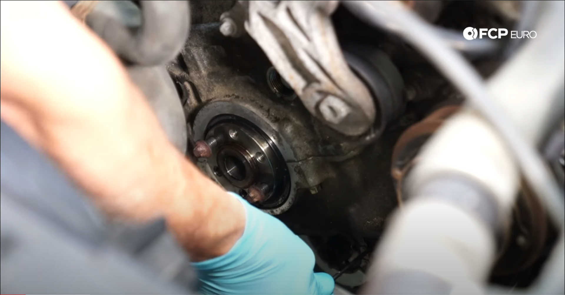
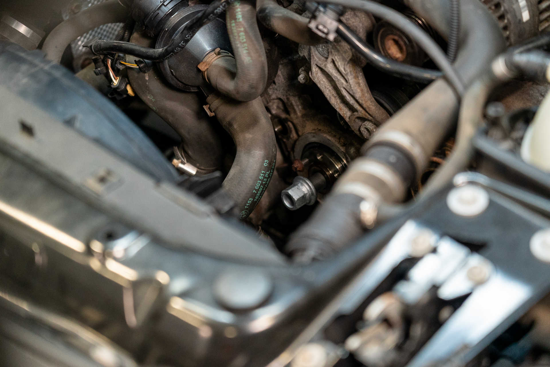
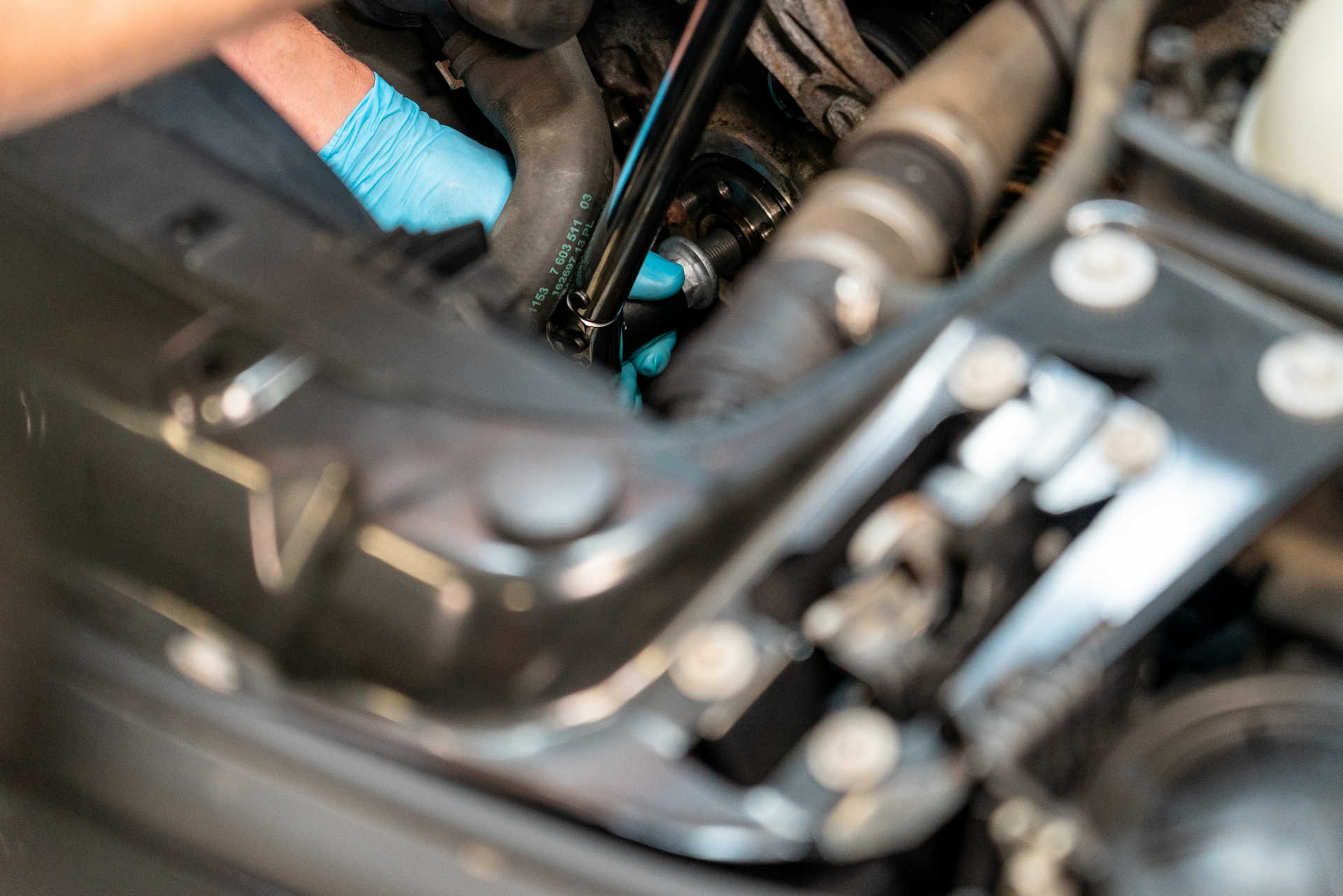
The new crankshaft bolt is a torque to yield bolt, meaning it is one-time use. Thread the new bolt supplied in the timing chain kit into the crankshaft and tighten it with a 22mm socket. The bolt gets torqued to 100 N m, plus another 270° of rotation.
Step 7: Install the timing chain guide pin plugs
Reinstall the timing chain guide pin plugs to prevent oil from leaking out of the engine once it is back together. Thread the smallest cap into the hole just under the driver's side camshaft. Torque the plug to 25 N m using an 8mm hex or Allen socket.
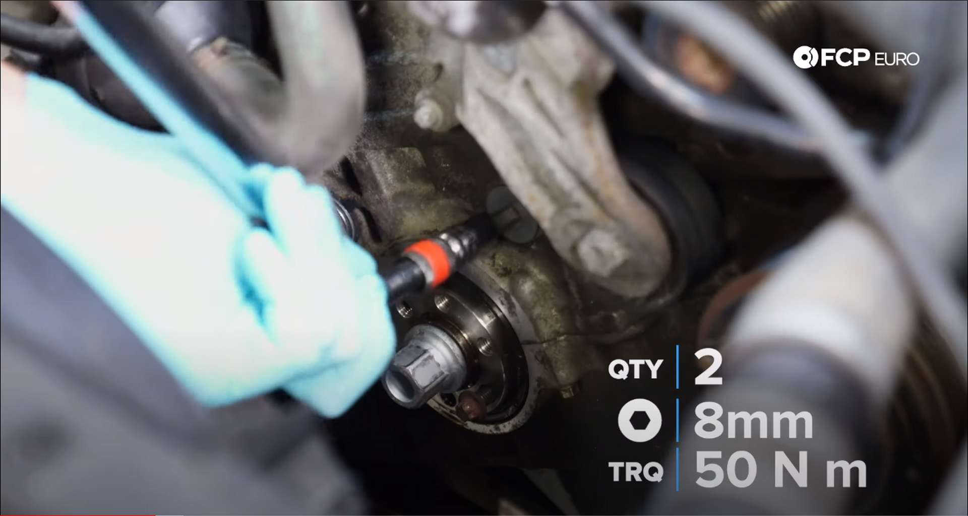
The lower plugs get tightened to 50 N m, using the same 8mm hex or Allen socket.
Step 8: Install the vibration dampener
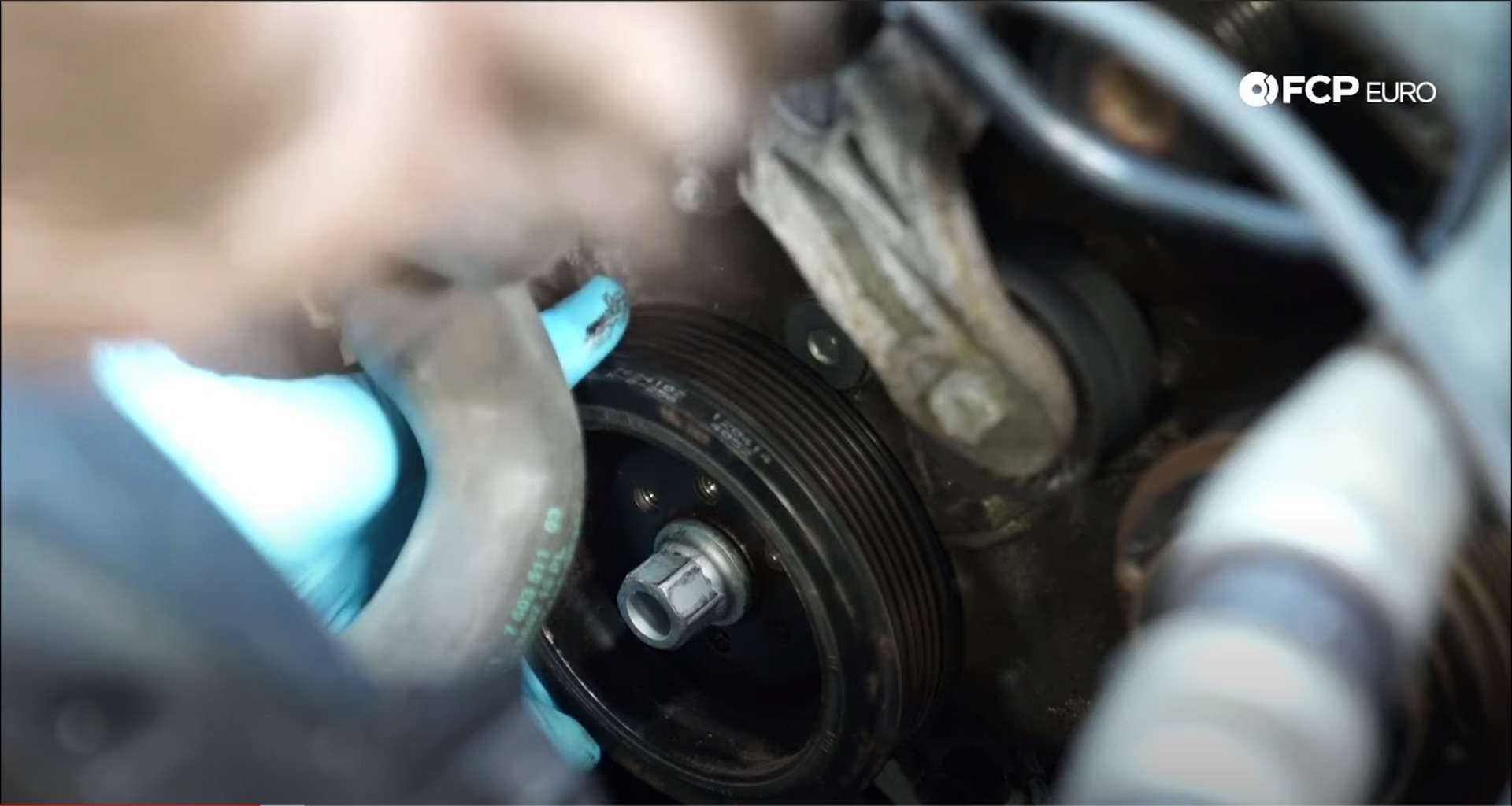
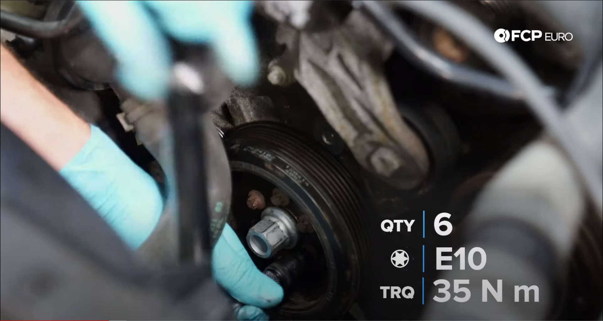
If you left the two bolts in the vibration dampener mount, remove them. Take the vibration dampener and seat it on the mount, lining up the bolt holes. Thread in the E10 bolts and tighten them in a star pattern to 35 N m.
Step 9: Check the timing
Start by removing the pins from the camshaft adjusters, then loosen the bolts for the green camshaft timing tool and remove it. Next, loosen the four top bolts on the cam lock tool, and remove the two mounting bolts. Then, pull the cam lock tool off of the engine. The tool sits tightly on the camshafts and will require some wiggling and force for removal.
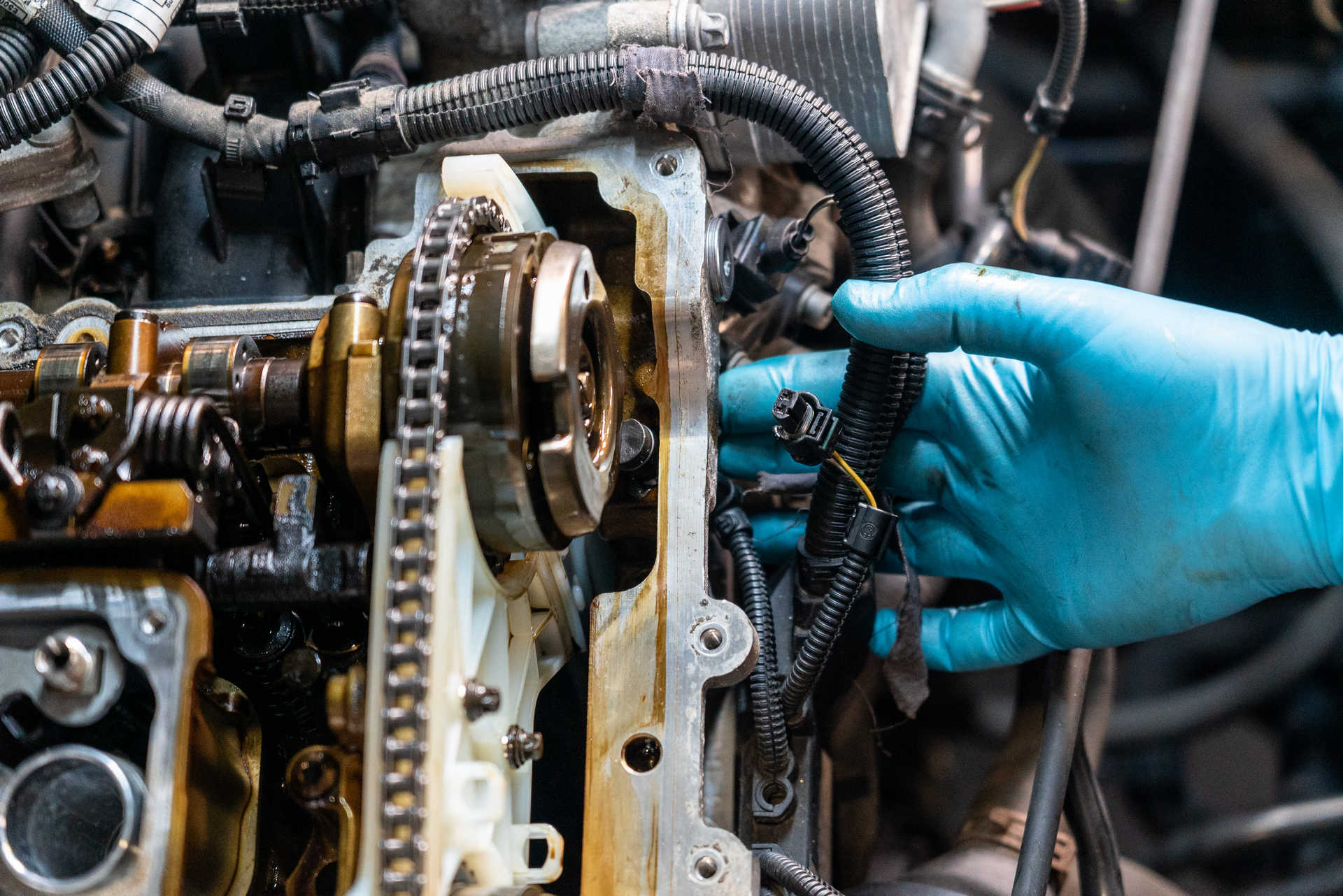
Clean the camshaft angle sensors of any metallic shavings and reinsert them into the timing cover. Secure them to the cover using the E8 bolts and torque them to 6 N m.
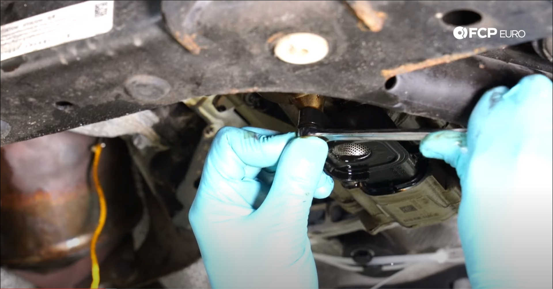
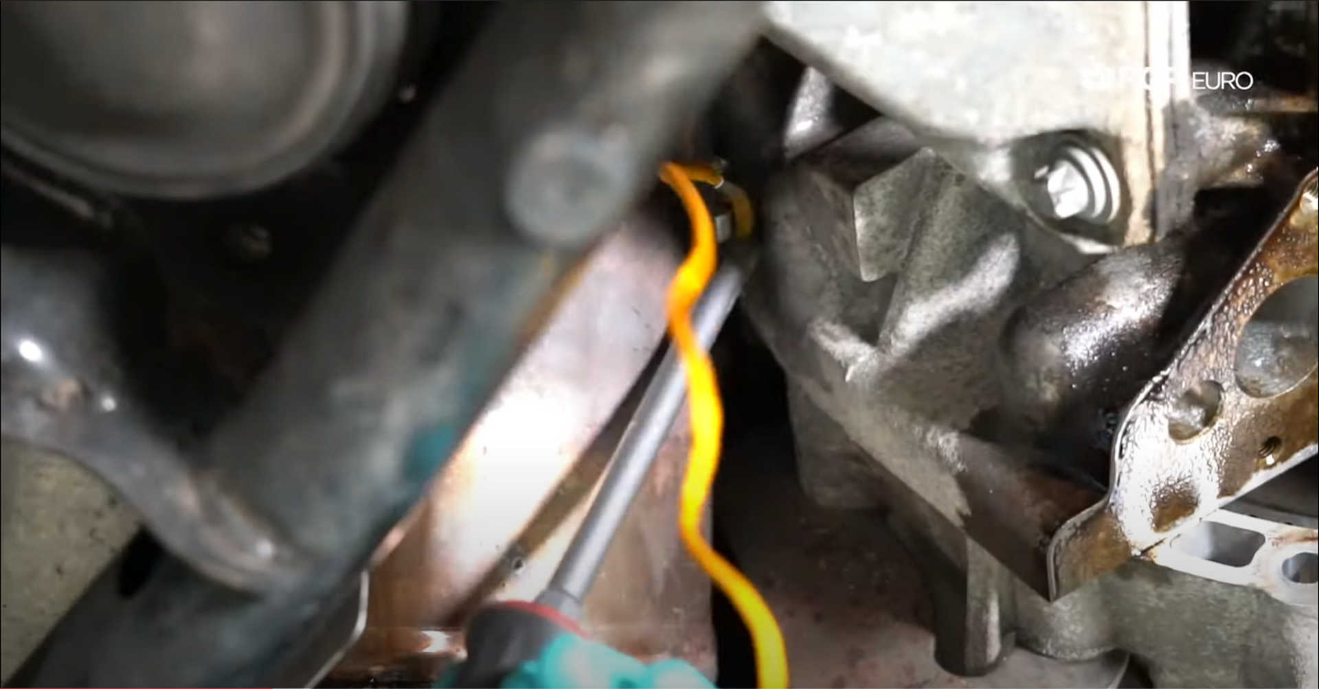
Next, remove the remaining locking tools. Remove whatever you have holding the flywheel locking tool in place and pull it off of the transmission. Then pull the balance shaft locking tool out from the oil pickup. Reinstall the M6 10mm bolt into the oil pickup and tighten it to 10 N m. Lastly, wiggle the flywheel locking pin out of the transmission and reinsert the plug.
Take a sharpie and make some marks on the flywheel, camshaft adjusters, and the vibration dampener. Use these marks to make sure everything lines up after the engine turns over. Use a 22mm socket on the crankshaft bolt to turn the engine over. Make sure the mark on the dampener makes two revolutions as that will be one full revolution for the camshafts. All of the marks should line up once this process is over if everything is in time.
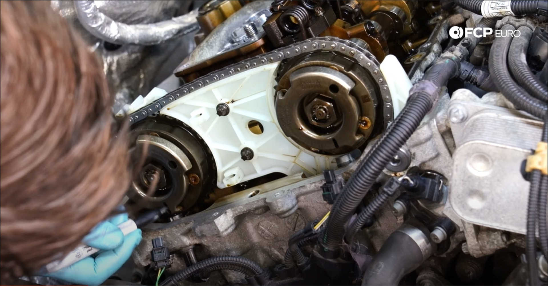
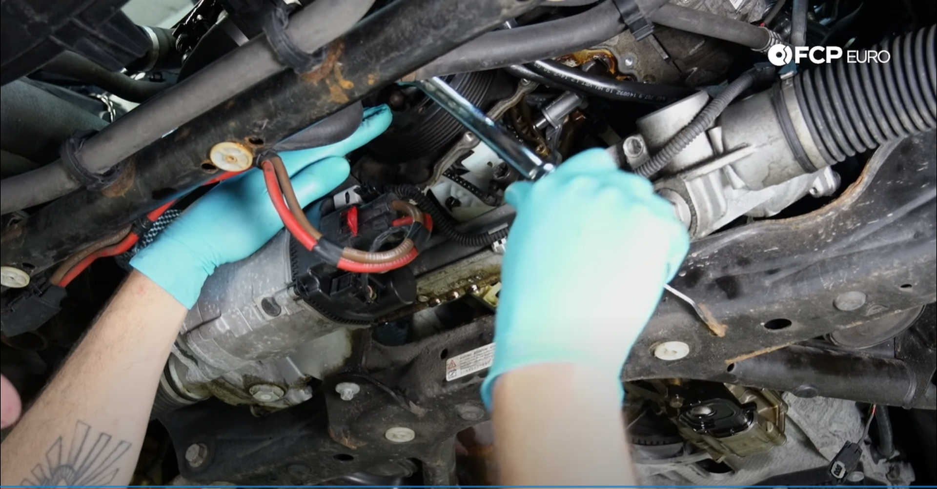
Additionally, you can check the timing by reinstalling either of the camshaft tools to see if they fit without having to rotate them.
Step 10: Install the new timing chain tensioner
Remove the timing chain tensioner tool, but don't release all of the tension from the rail. Having a partner handy will help make this process easier. Also, have the new tensioner within reach once the tool is removed.
Grab a set of channellocks and grip the knurled part of the tensioner. Turn it toward the back of the engine to loosen it enough to spin it with your fingers. As you thread the tool out, watch the chain guide move. When it starts to move, put one hand in the engine to keep the pressure on the rail as you back out the tensioner tool with the other.
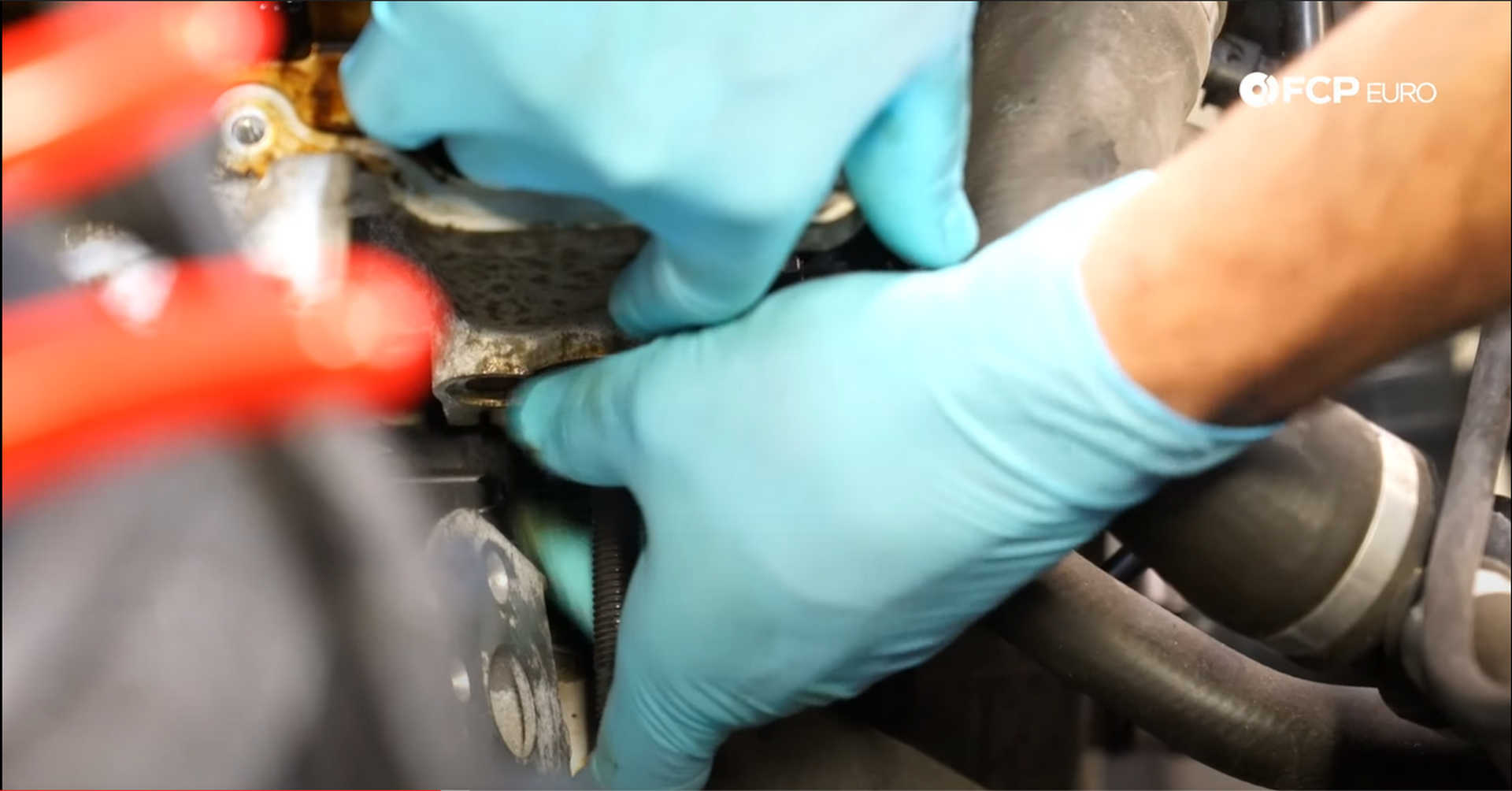
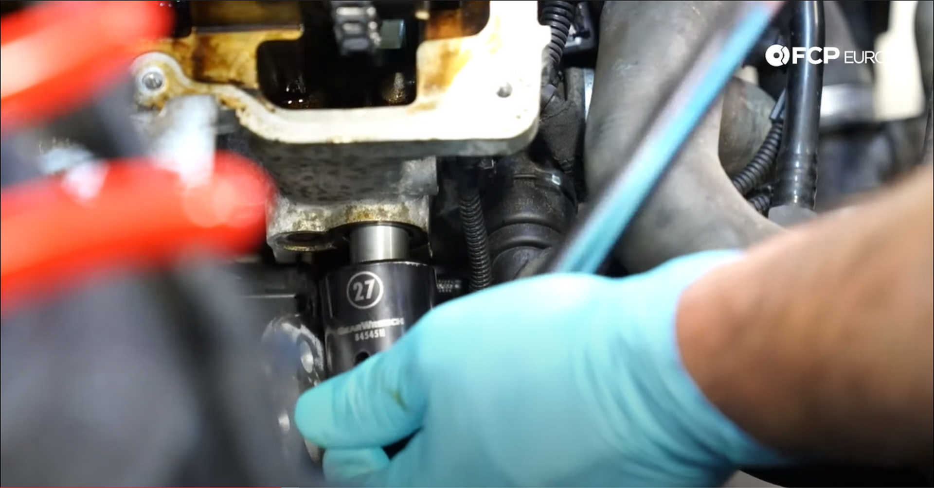
Thread the new tensioner into the engine once. Pull your hand off of the guide when you feel the tensioner makes contact with the guide. Use a 27mm socket to tighten the tensioner to 80 N m.
Step 11: Reinstall the oil pan
Loosen the engine mounts and jack the engine up off of the mounts. We found it easiest to remove the driver's side engine mount entirely. Remove one of the E12 bolts holding in the engine mount arm and loosen the other two allowing it to move around.
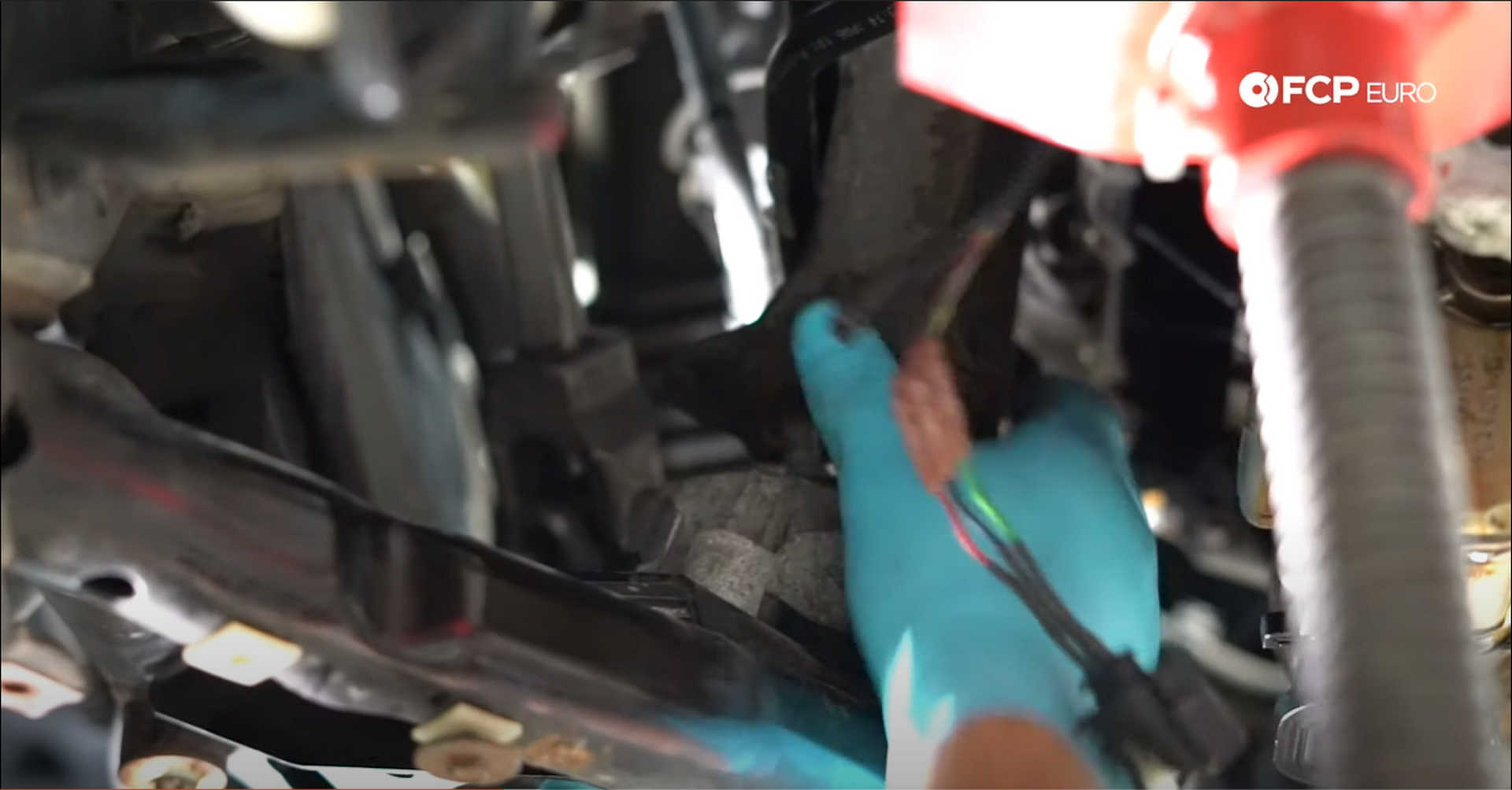
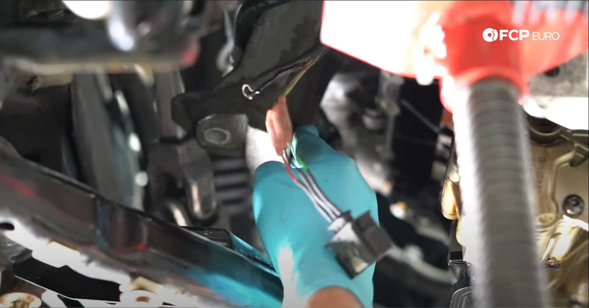
Jack up the engine to allow the engine mount to come out of the arm and the subframe. The removal of the mount gives much more access to the oil pan bolts. Use some brake clean or a degreaser and a rag to wipe down the area where the oil pan seals to the engine.
Next, fit the new oil pan seal into the channel in the oil pan. Take your time figuring out the orientation of the seal. Use the straight sections in the seal to determine where it should sit in the pan. Have the new bolts at the ready and install the new pan—jack up the engine as much as needed to slide the oil pan into place.
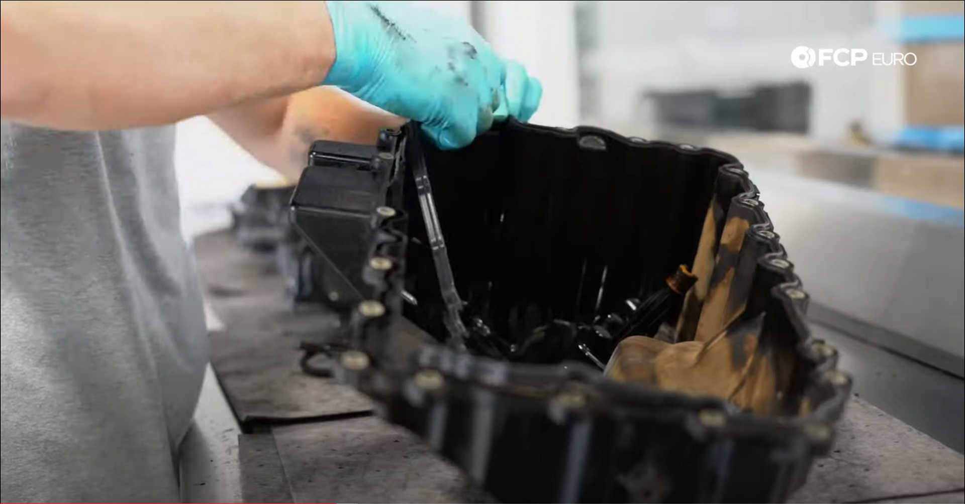
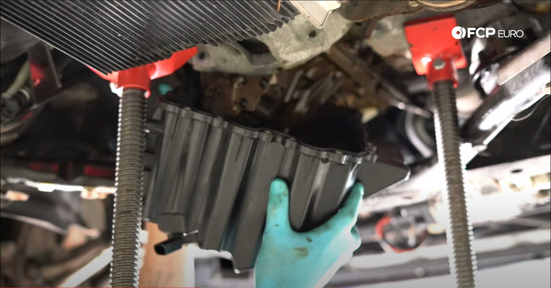
There are twenty-two (22) E8 bolts that secure the oil pan to the engine. Two of those bolts look slightly different and have specific locations as they thread into the crankcase. The two special bolts thread into the middle two spots at the back of the oil pan. Tighten all of the bolts to 12 N m.
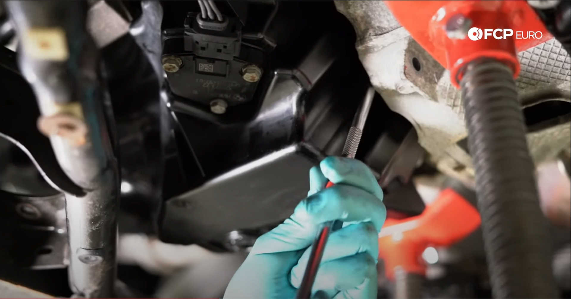
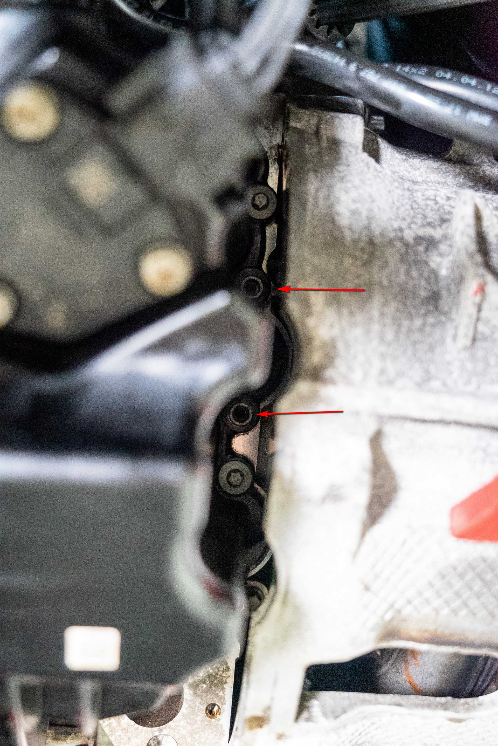
A pair of transmission lines need to be reattached to the oil pan. Use an E8 socket to tighten the bolts securing the transmission lines. The first bolt goes in just above the front subframe, and the second bolt goes in above the oil level sensor, which can now be reconnected to the car.
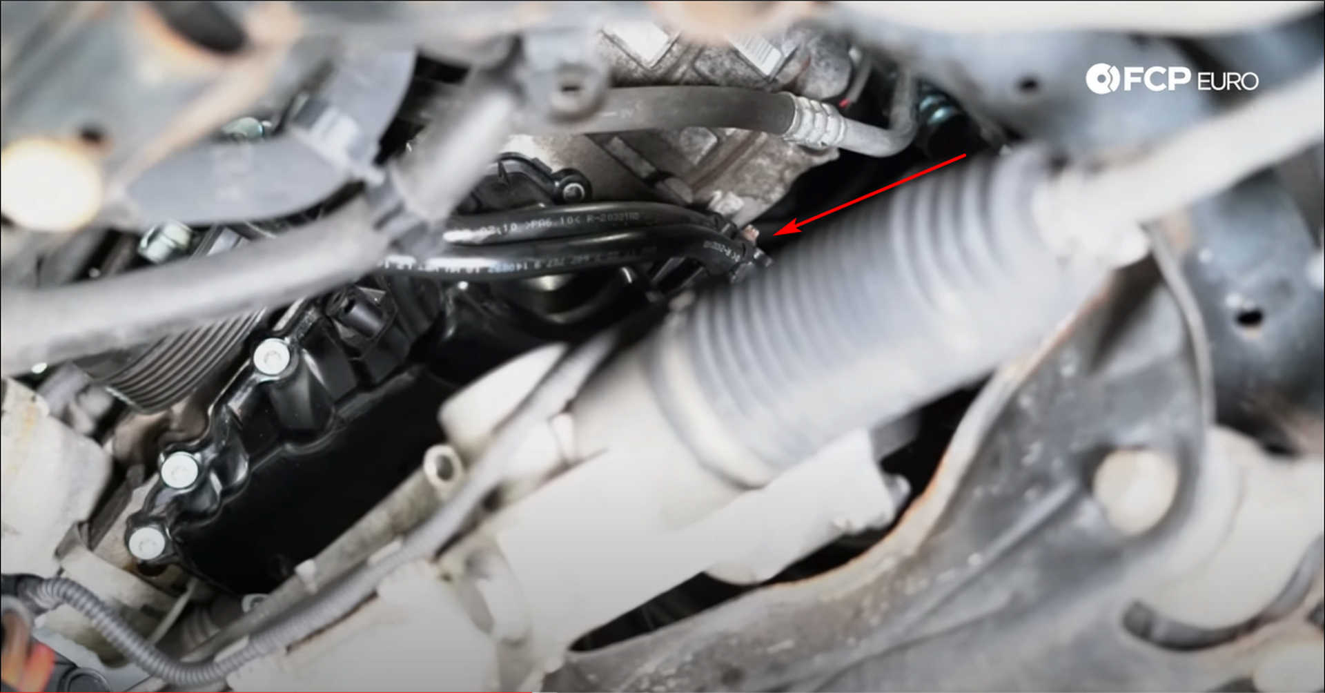
Refit the removed engine mount arm bolt and tighten all three of them with an E12 socket. Next, fit the engine mounts back into the subframe and thread in the bolts to get it in the right orientation. Then, lower the engine down onto the mounts. Tighten the nut used to secure the mount arm to the mount with a 16mm socket and an E12 socket for the three bolts securing the engine mount to the subframe.
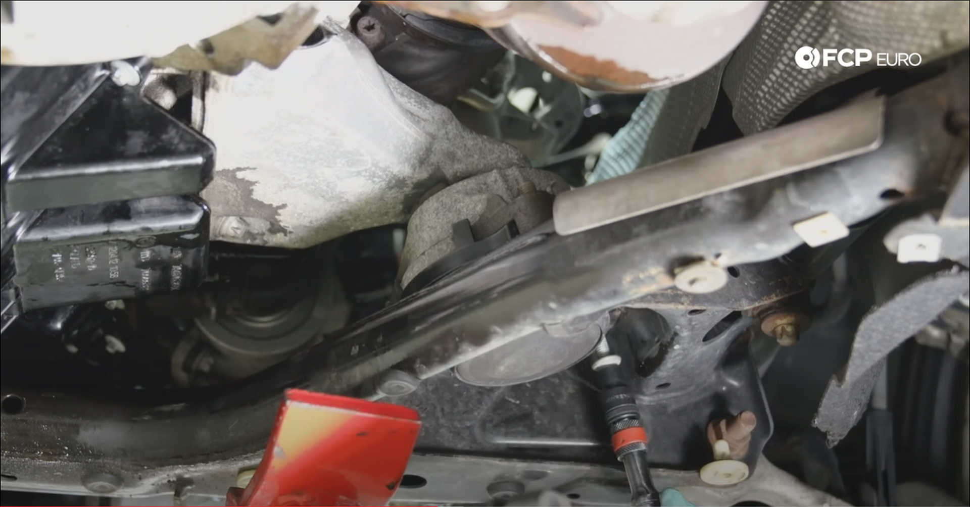
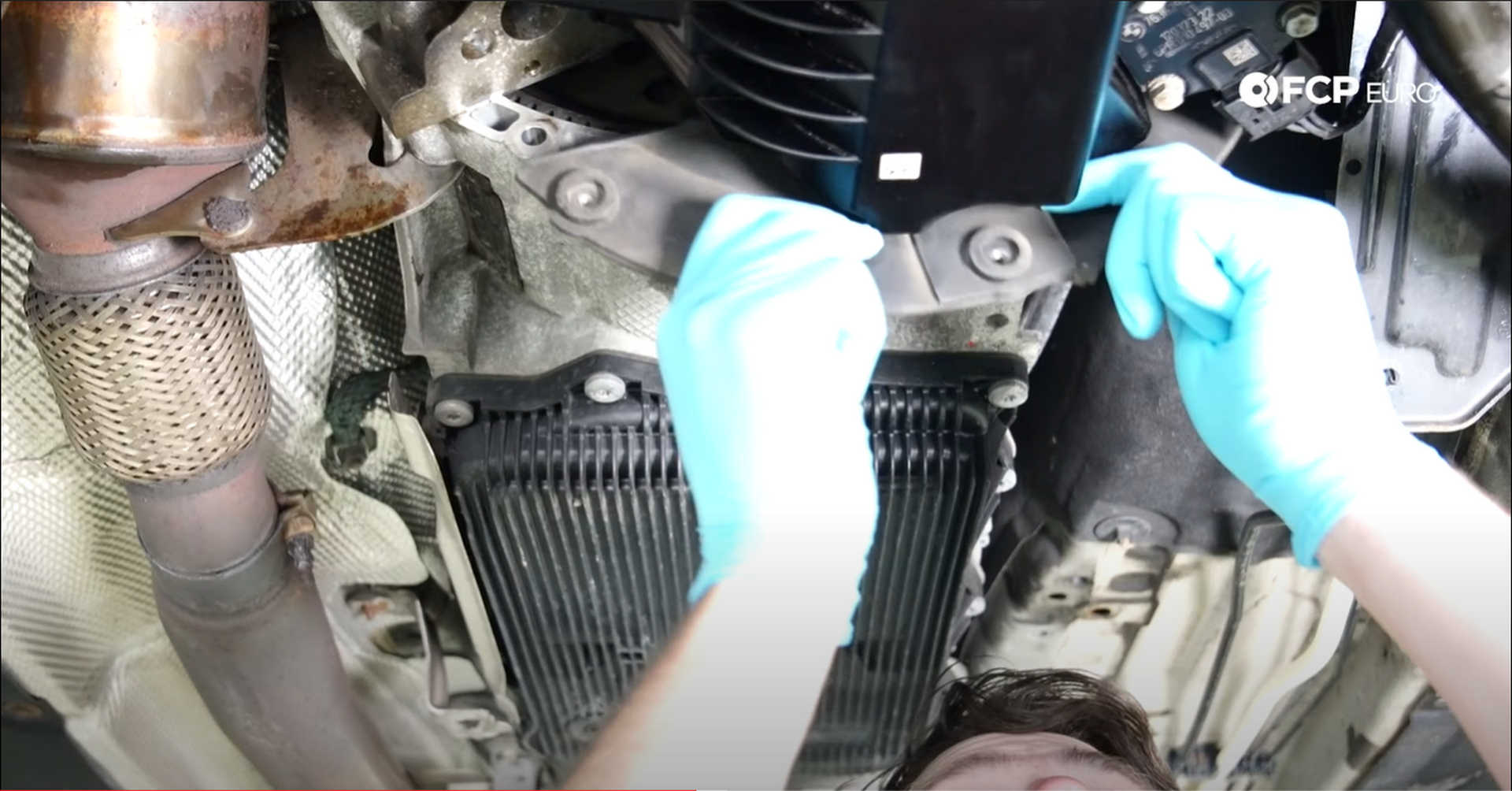
Refit the transmission's dust shield and secure it to the bell housing with three 10mm bolts. Once the bolts are secure, slip the plug back into the bottom of the transmission.
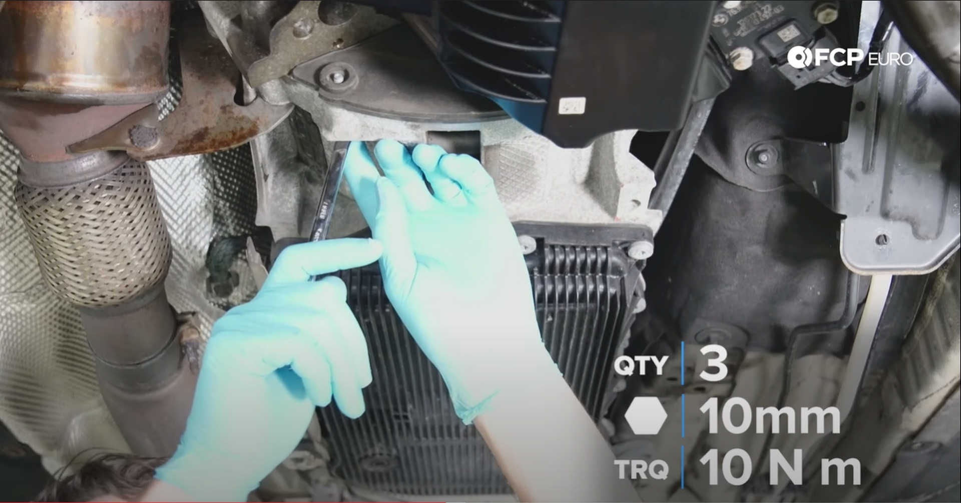
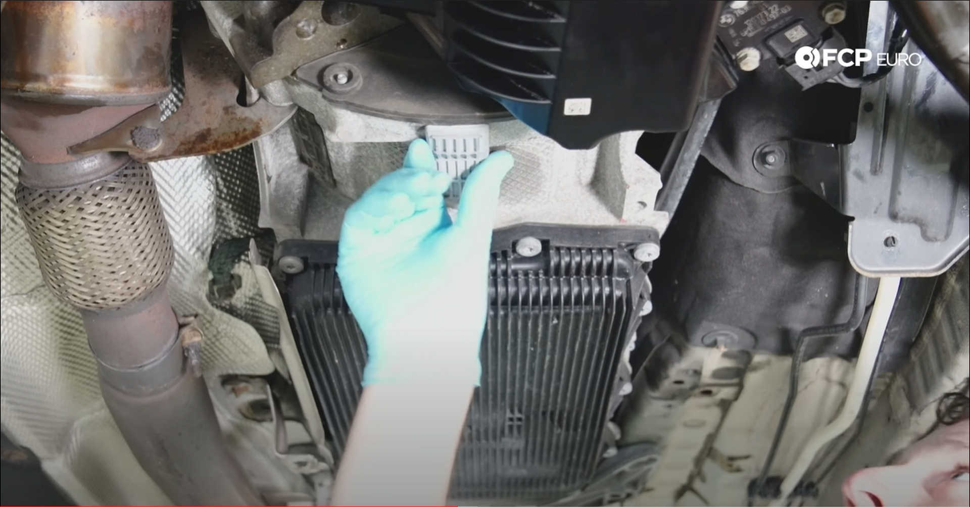
If you needed to use the manual lockout on the side of the transmission to put it into neutral, back the bolt out with a 5mm hex wrench until the bolt isn't making contact with the lever.
Step 12: Reinstall the accessory belt
Take the accessory belt and seat it onto the vibration dampener. Take a 16mm socket and rotate the ratchet to the right to pull the tensioner back. With your other hand, get the belt around the alternator pulley and the A/C compressor. Release the hold on the tensioner once all of the ribs in the belt are sitting in their grooves.
Step 13: Refit the turbocharger parts
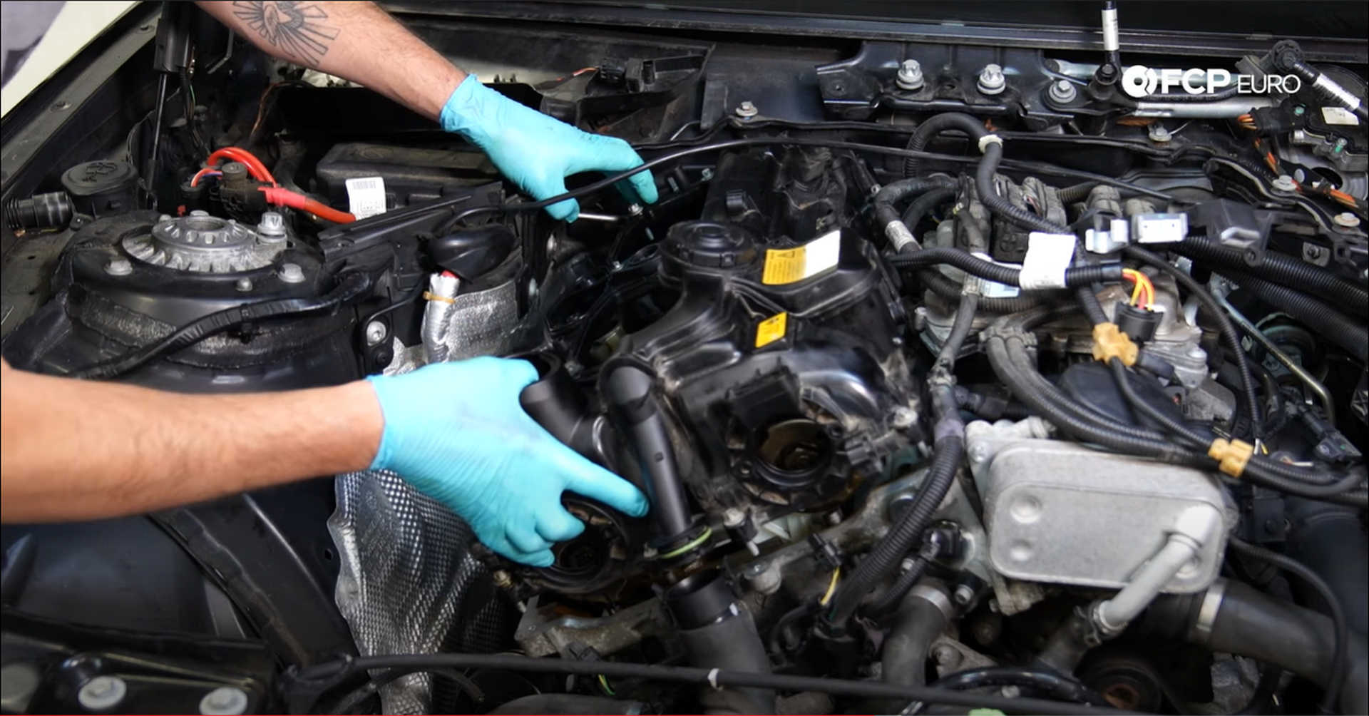
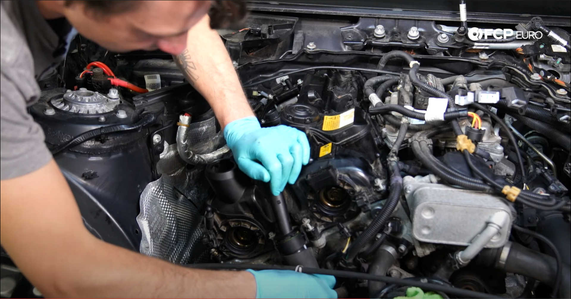
First up, refit the turbocharger's intake plenum. Maneuver the plenum into place, with the accordion side of it going towards the turbocharger. Clip the airline on, plug in the sensor, and clip the coolant line under the plenum towards the driver's side of the engine bay.
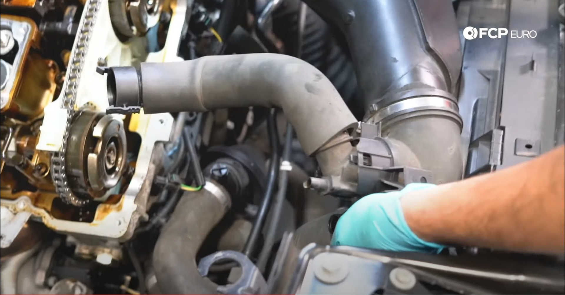
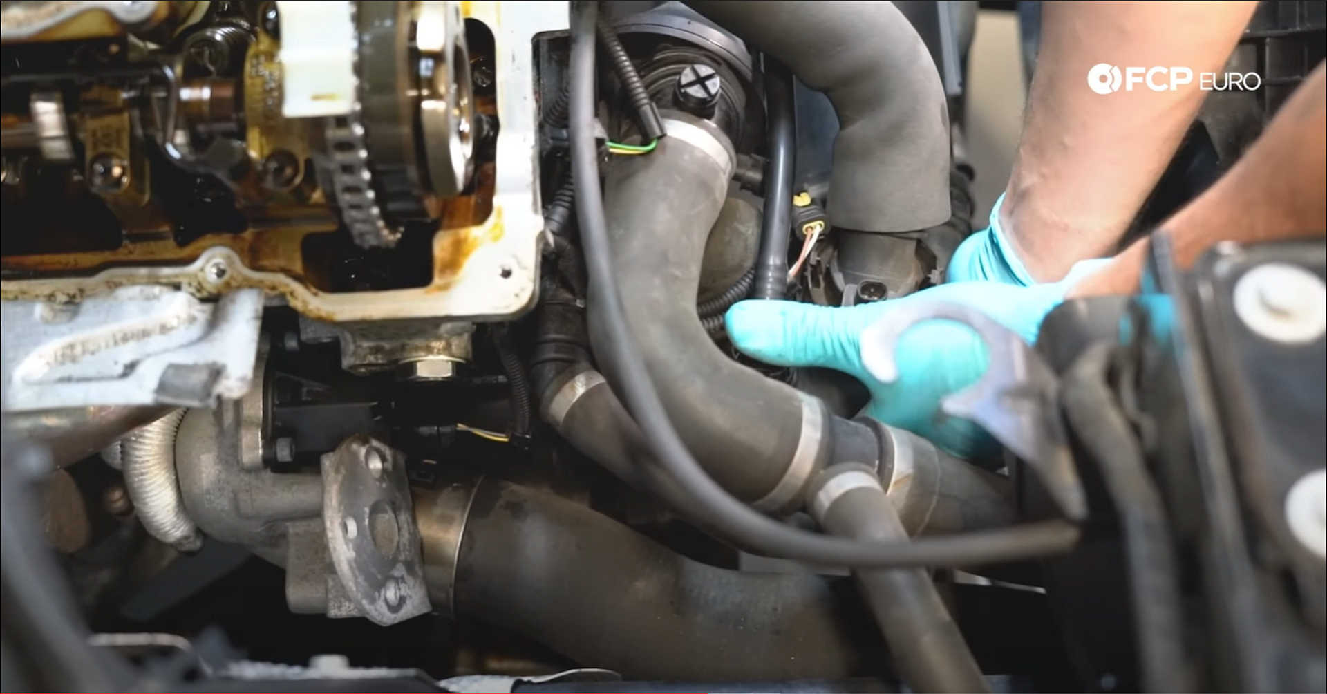
Install the 10mm nut under the intake to the turbocharger and tighten it down to secure the two together.
Next, slide the wastegate actuator through its mounting bracket and secure it with its three 10mm nuts. Clip the actuator rod to the wastegate once the actuator is secured. Leave the solenoid attached to the actuator; it will mount to the valve cover.
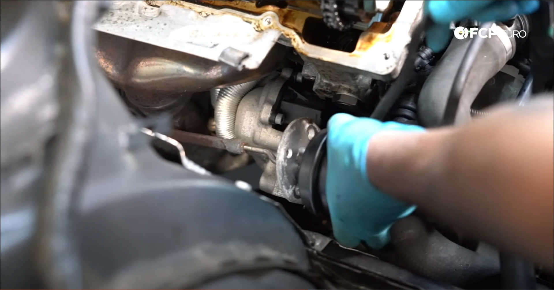
Step 14: Reinstall the valve cover
Start by taking a rag with brake clean or degreaser and wipe down the surface of the engine block that the valve cover sits on. Then, install the rubber gaskets into the valve cover. The largest gasket and the two rectangular ones get installed on the inside of the cover, and the oval-ish one gets installed on top. All of the gaskets go on one way, so be sure that they are all in the proper orientation.
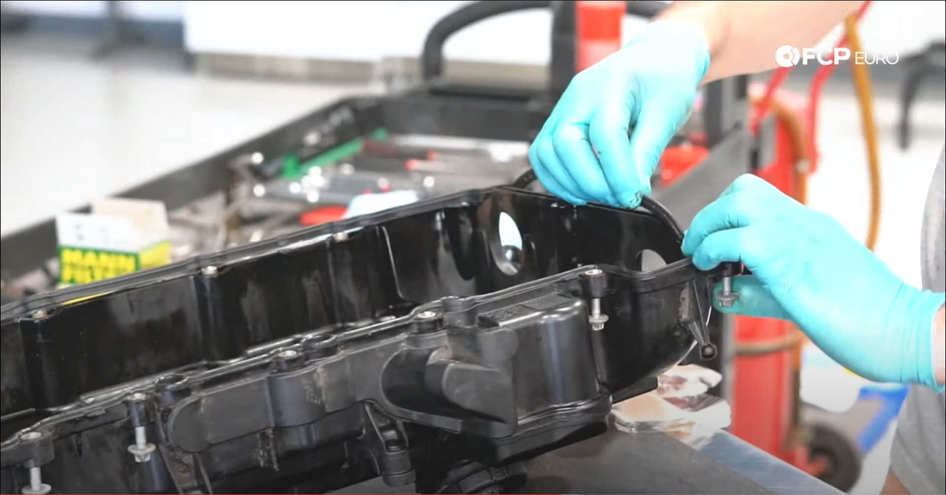
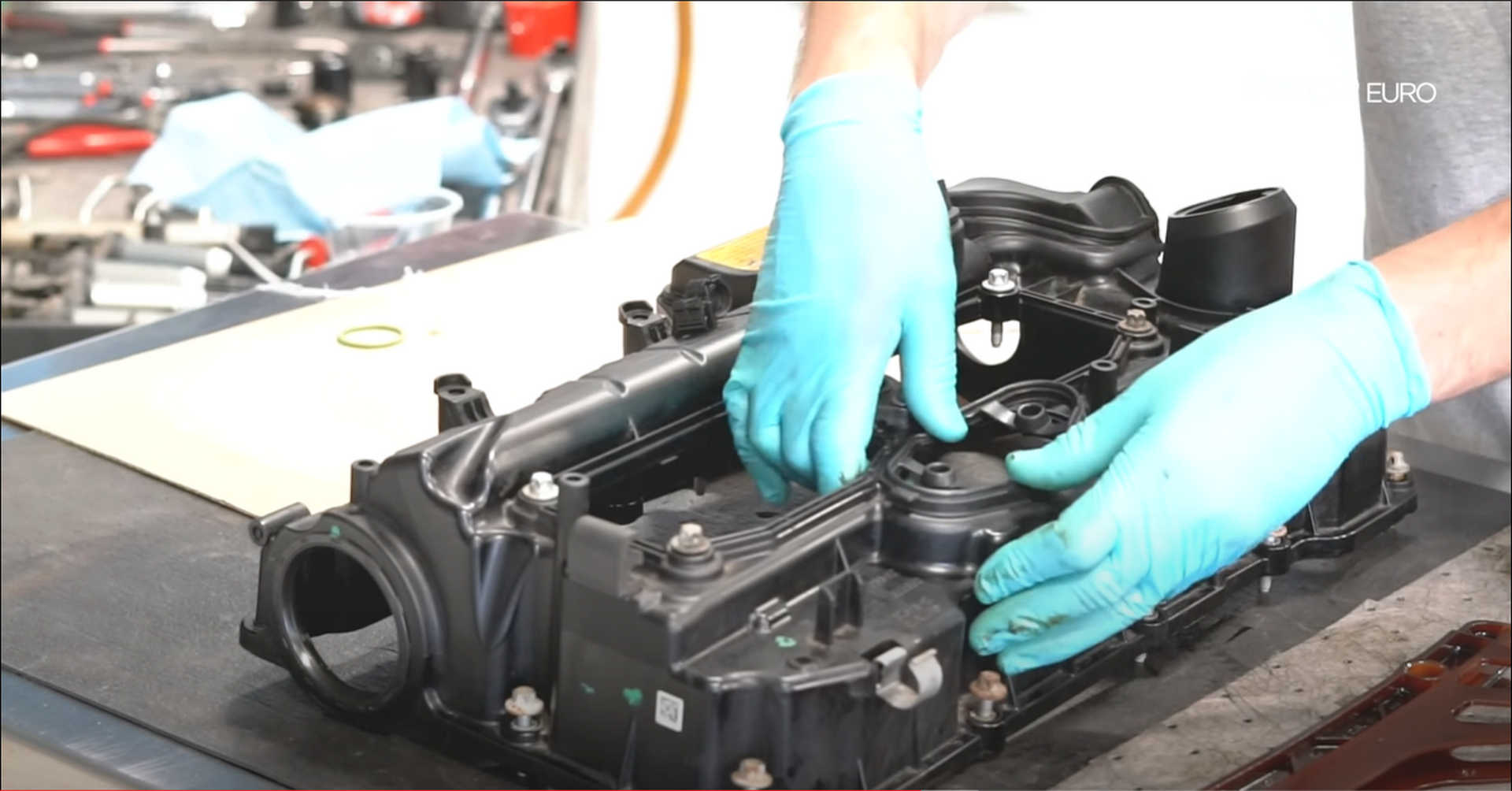
Remove the old crankcase vent line o-ring and replace it with the one supplied in the kit.
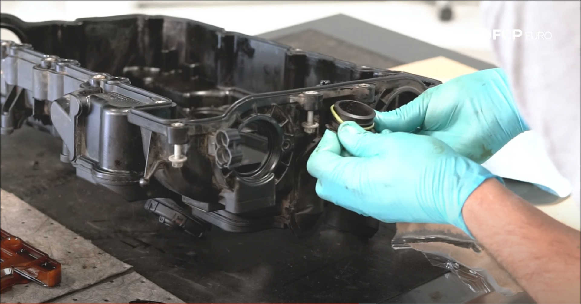
When installing the valve cover, be very careful not to crack it. A new cover will cost you $455. Make sure all of the wiring and fuel lines are out of the way before dropping the cover on. Rub some oil on the Valvetronic plug on the cylinder head, as this is the first thing the cover comes in contact with, and it needs to slide over it. Lightly thread in some of the bolts to help align the cover into place. Once the valve cover is seated, connect the vent line at the front of the cover.
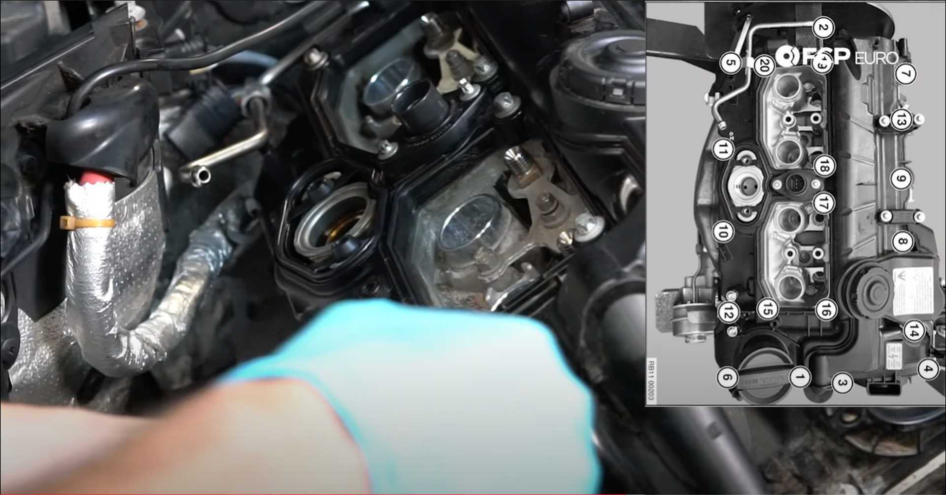
Snug the valve cover bolts against the cover, but don't tighten them down. Follow the specific BMW pattern shown below when tightening and torquing down the valve cover bolts. Use an E12 socket to torque them to 9 N m. To be extra careful, tighten them all halfway before starting the pattern over again and setting the final torque value.
Step 15: Install the camshaft timing adjusters, boost control solenoid, and vacuum pump
Before fitting the camshaft timing adjuster to the valve cover, wipe some fresh oil around their o-rings. Next, seat them into their respective holes and drive in their fasteners with an E7 socket. Tighten them to 5.5 N m.
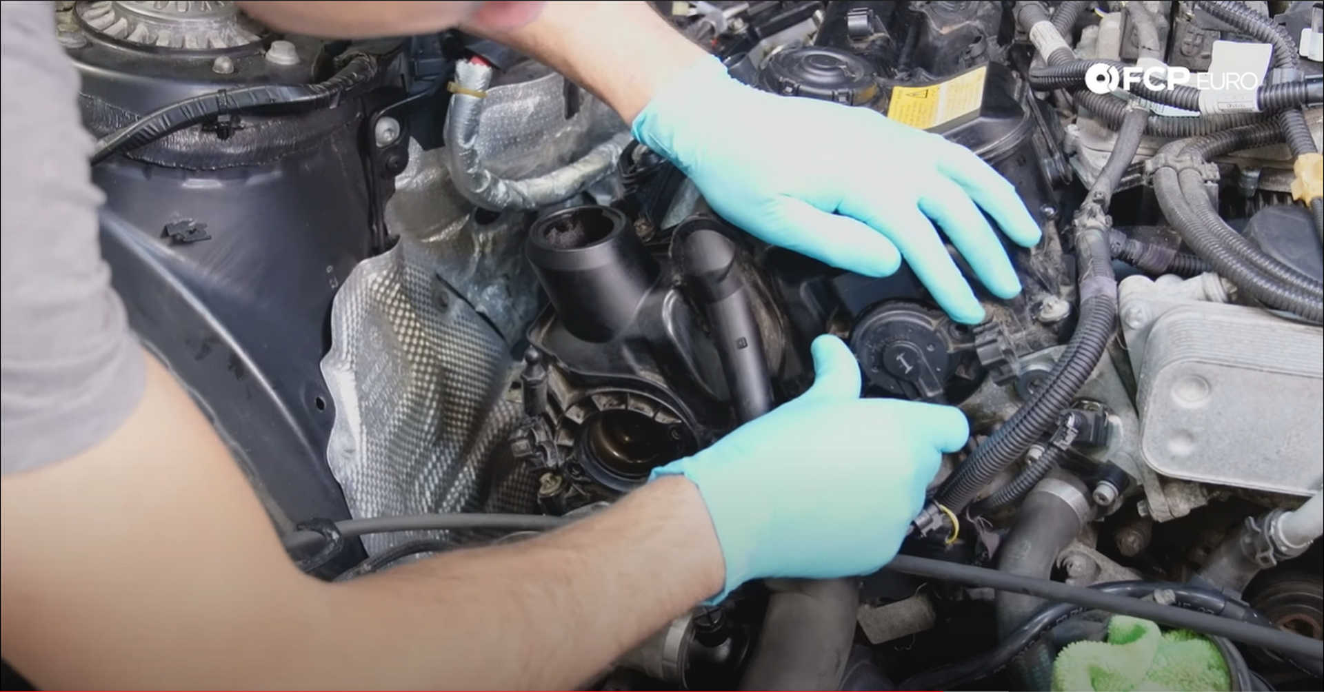
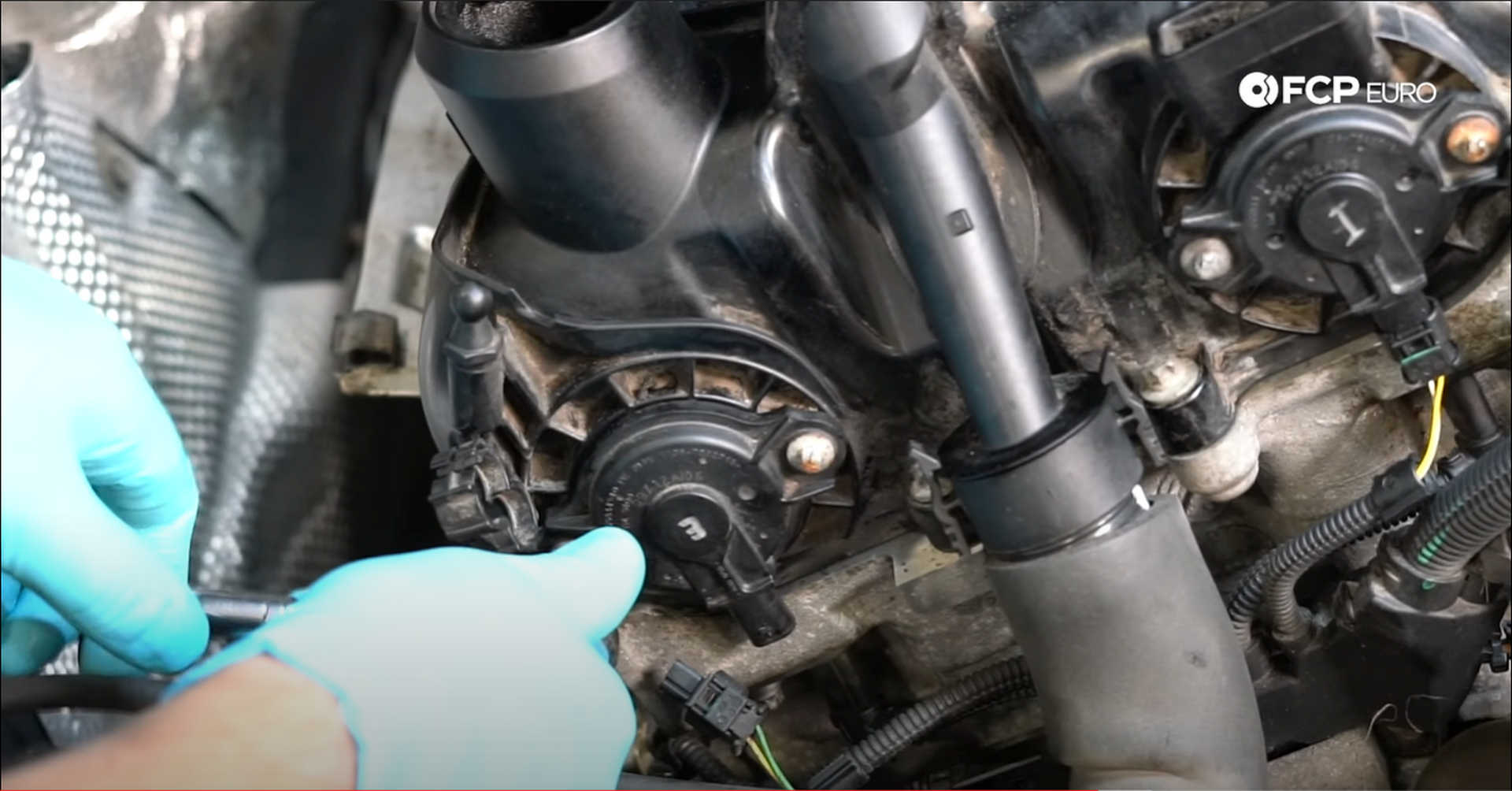
Plug the actuators in once they are torqued down.
Next, the boost control solenoid can be mounted. Secure it to the valve cover using its two T30 screws and torque them to 5.5 N m. The boost line clips into the heat shield below.
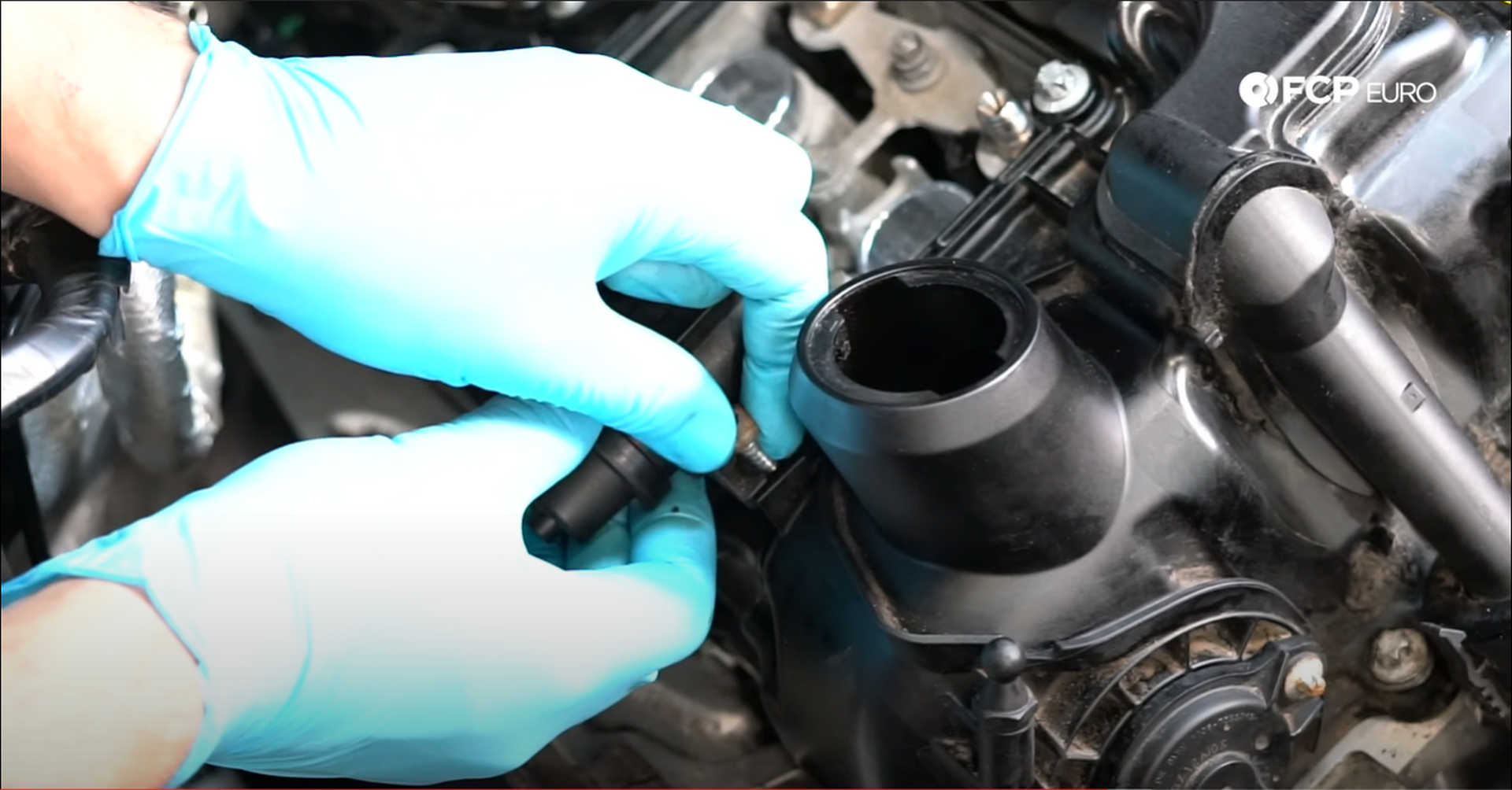
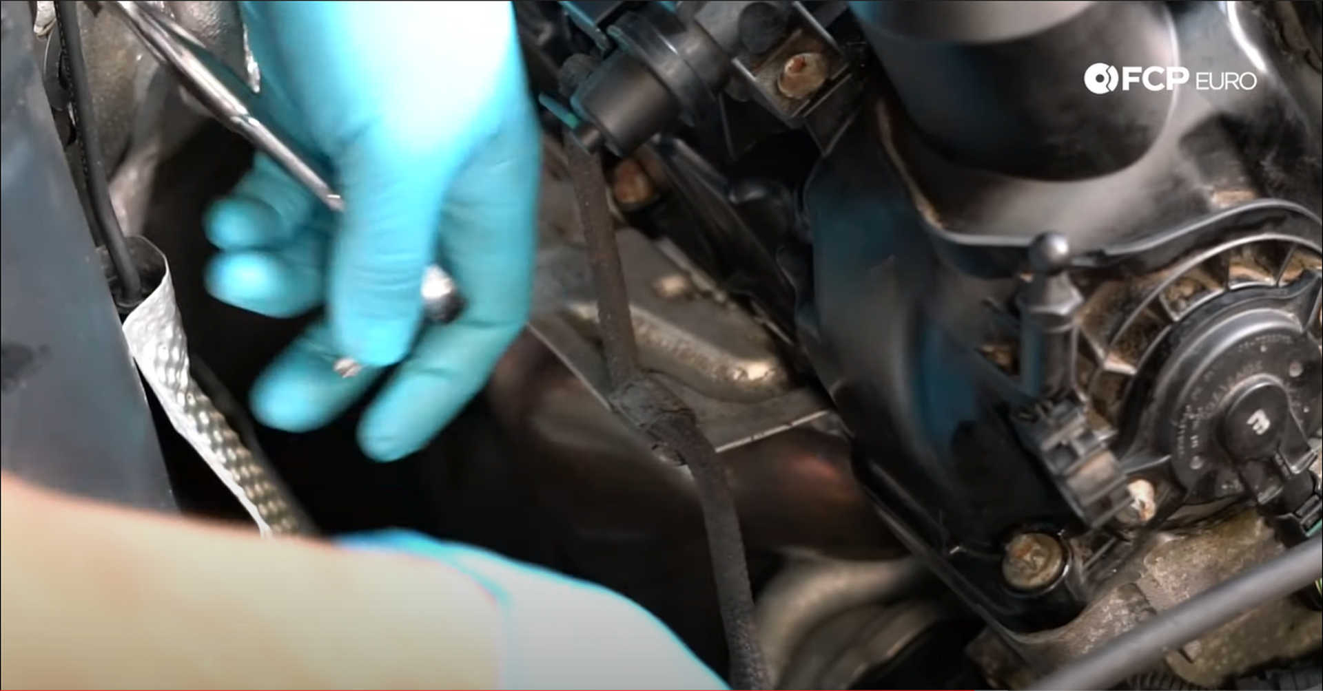
The vacuum pump sits at the back of the valve cover and runs off of the intake camshaft. There are two flats machined into the back of the camshaft that correspond with the drive on the vacuum pump. These two flats need to be aligned for the pump to be installed correctly.
Slide the pump in between the cowl and valve cover, with the larger round vacuum line connection facing the driver's side of the engine bay. Feel around on the back of the camshaft to get an idea of where the flats are positioned, and spin the drive on the pump to match that. Slip the drive onto the camshaft and then feel around with the bolts until you locate the threaded holes and can secure the pump to the cylinder head. Use a T40 bit socket to tighten down the bolts.
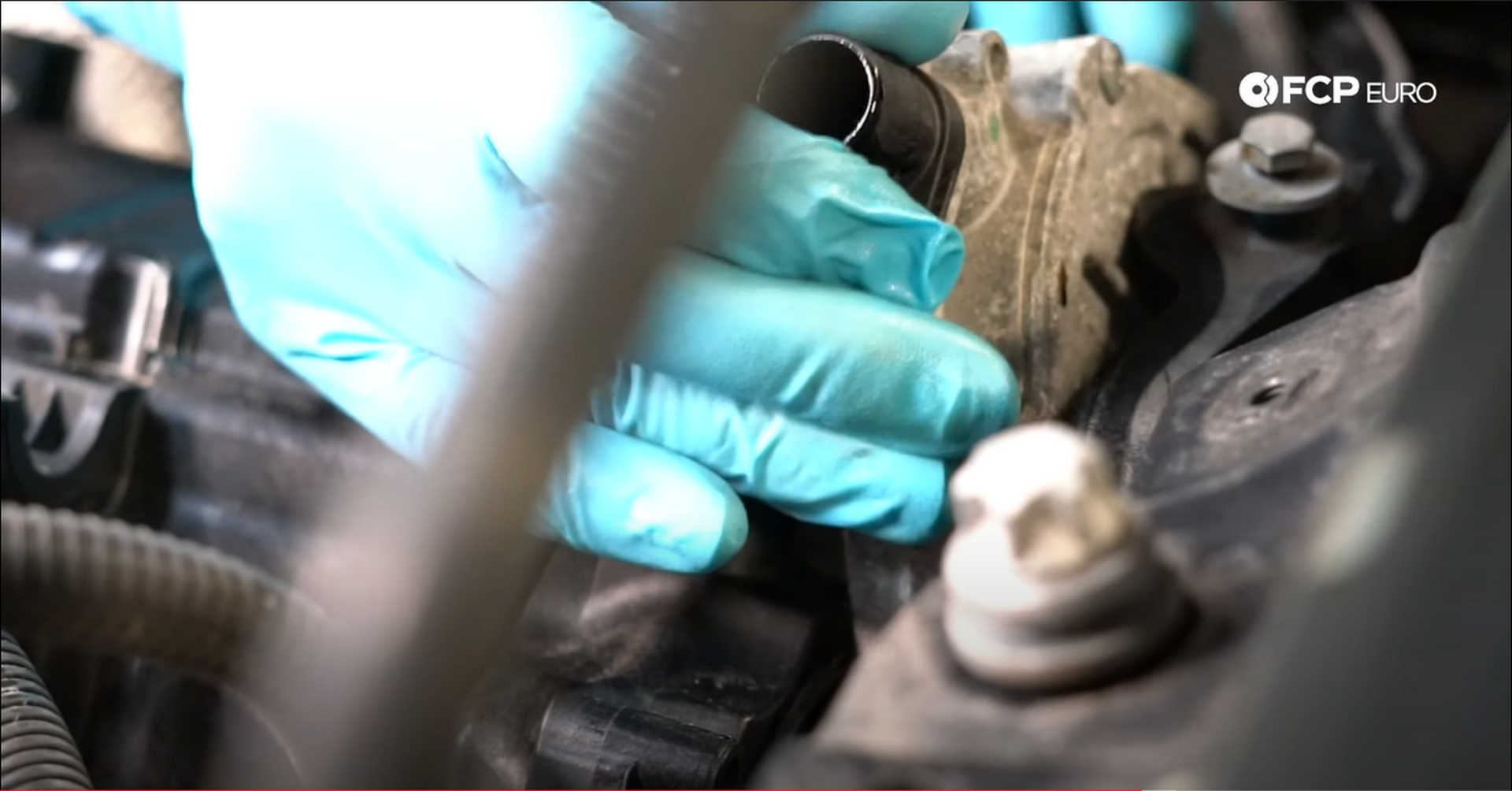
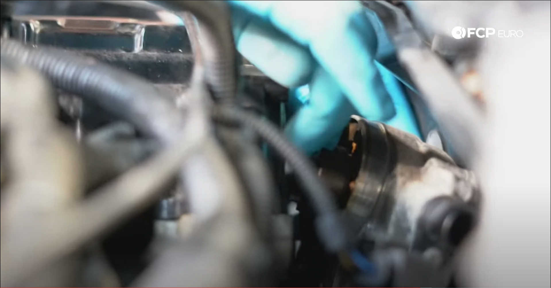
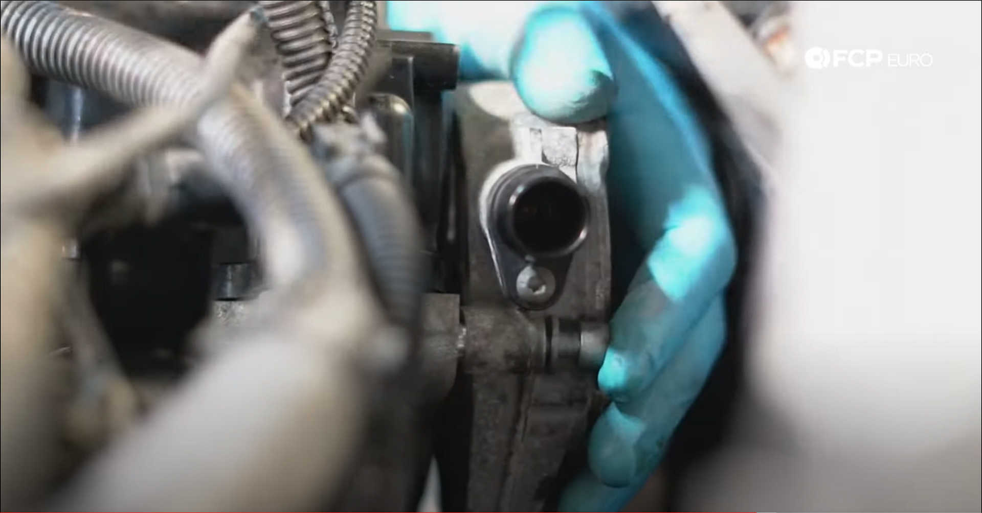
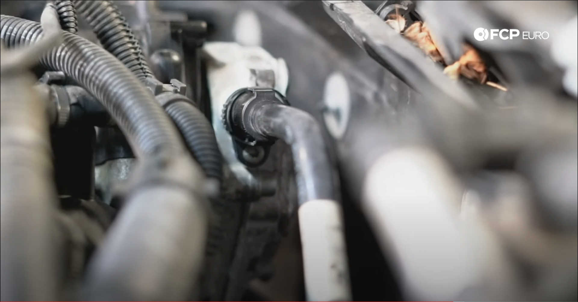
After the pump is mounted, reconnect the vacuum line to the pump and clip it into the firewall.
Step 16: Reinstall the fuel delivery system
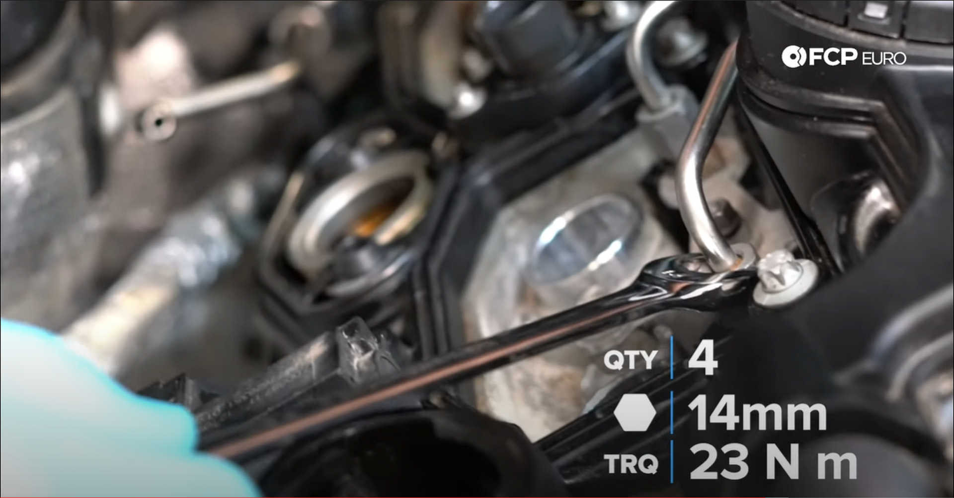
Take the fuel rail and situate it on the valve cover. The rail itself is mounted to the cover by two clamps with two bolts each. Before threading those bolts in, get all of the fuel lines started on their injector's threads. Use your fingers to thread them on so you don't cross-thread them. Use a 14mm wrench to tighten the lines to the injectors. Gently snug the lines and then thread in the bolts for the rail's clamps.
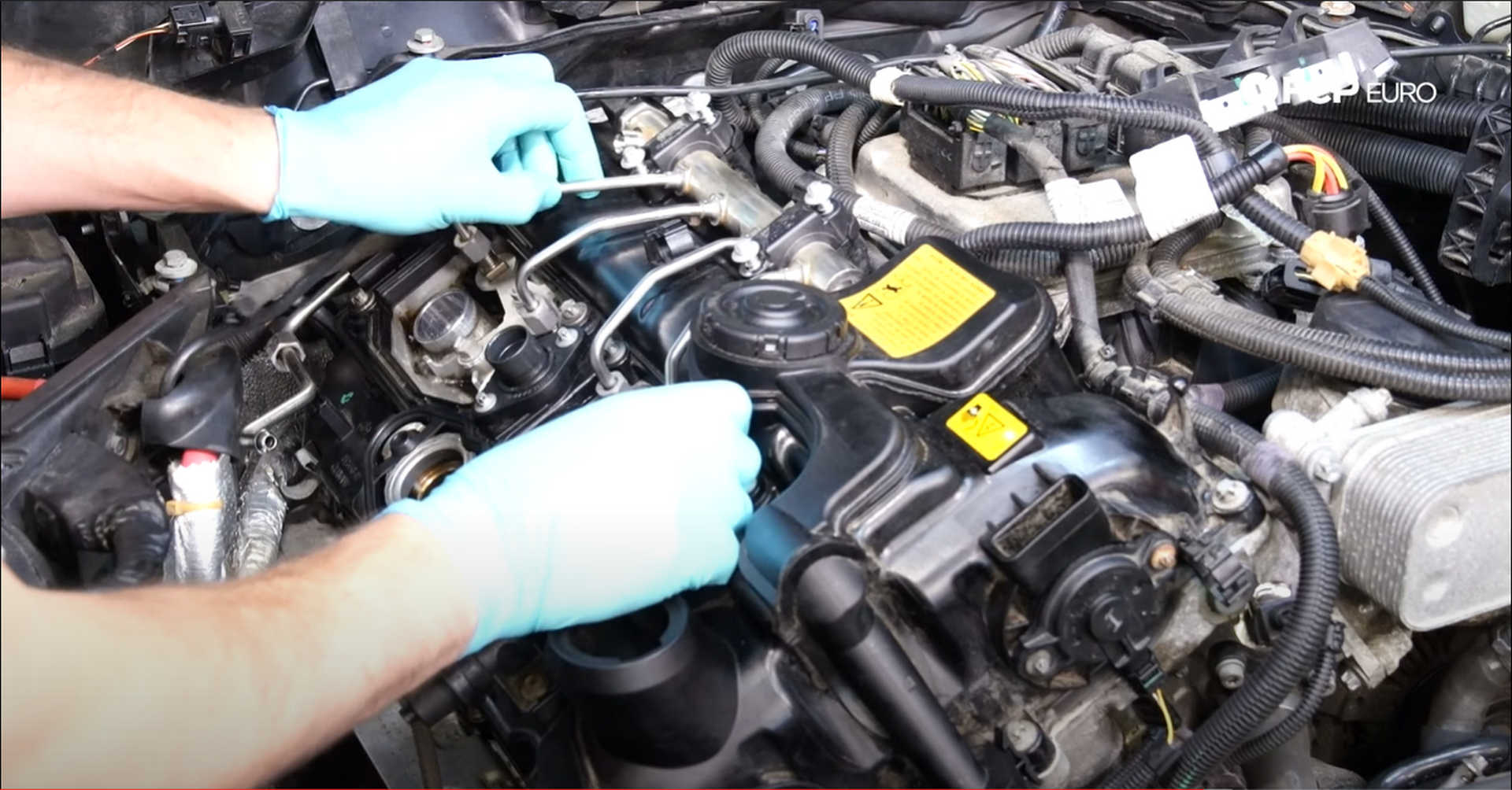
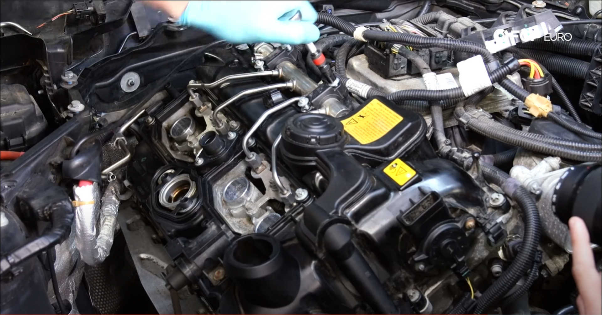
Use an E8 socket for the fuel rail clamp fasteners and torque them to 8 N m. Plug the rectangular connector on the wiring harness into the back of the fuel rail.
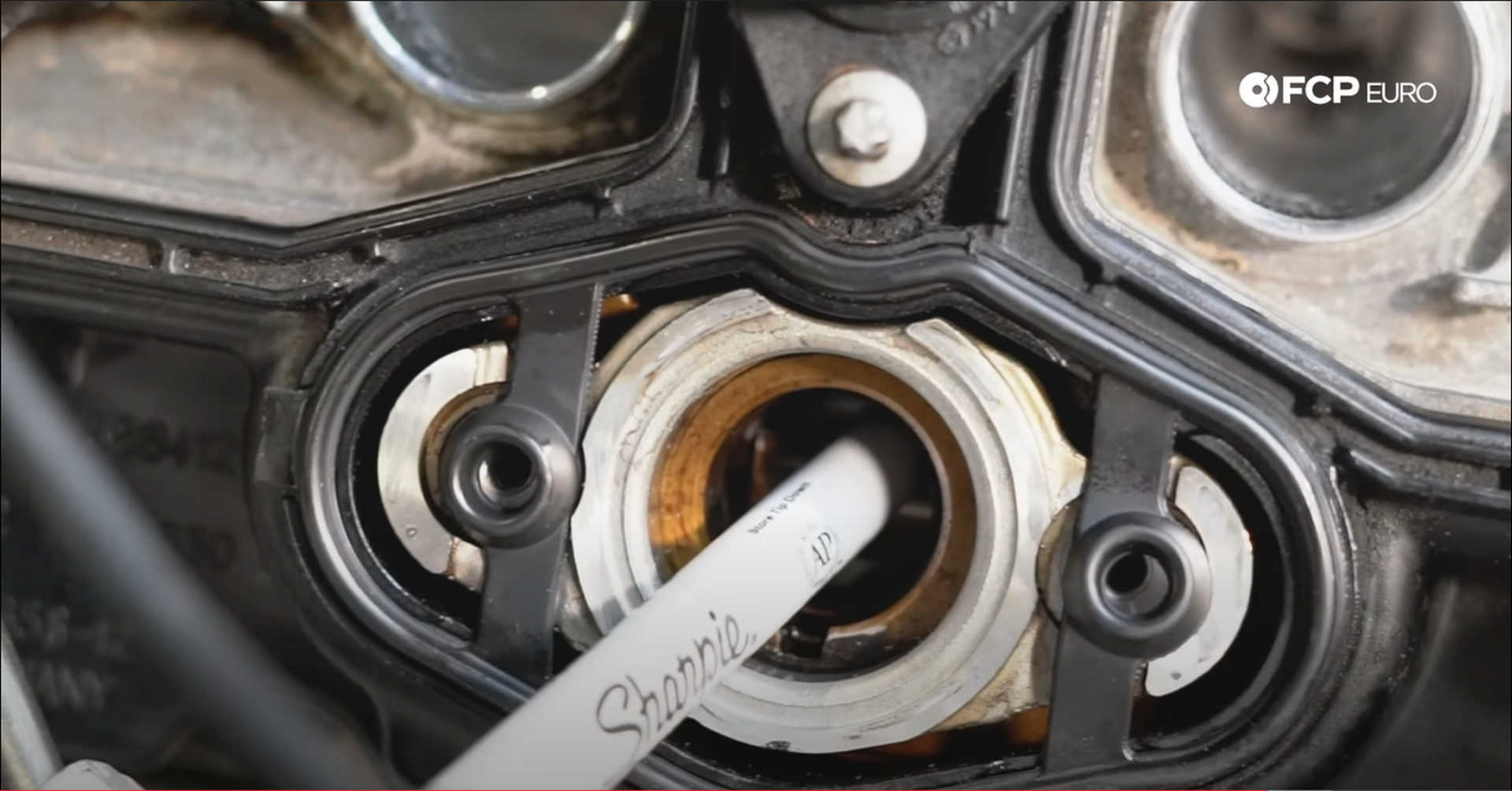
A lobe on the exhaust camshaft interacts with the high-pressure fuel pump to send fuel into the engine. The lobe must be at its bottom-most point when installing the fuel pump to prevent any damage being caused. Similar to finding top dead center with the screwdriver, turn the engine over with something like a sharpie marker in the hole and watch for when the sharpie gets to its lowest point. When it reaches that point, install the fuel pump.
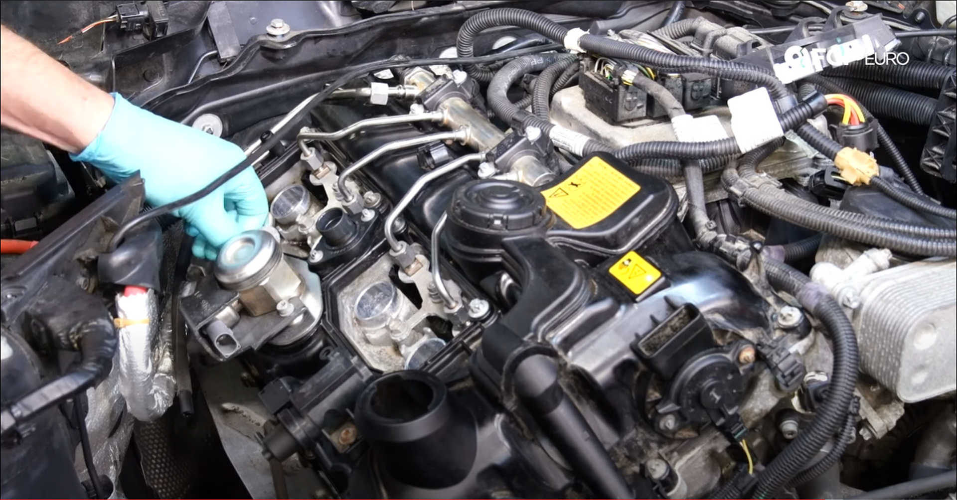
Slide the guard onto the fuel pump and situate it onto the valve cover. Sit the pump-to-rail feed line in its clip and start threading in the two mounting bolts. Start the threads on the feed line to the pump and the feed line from the pump to the rail. Then, tighten down the two mounting bolts with a T30 bit socket and torque them to 12 N m. Go back and forth on the two bolts to keep even pressure in the pump until you reach the 12 N m. Tighten the two fuel line connections with a 17mm wrench and torque them to 30 N m.
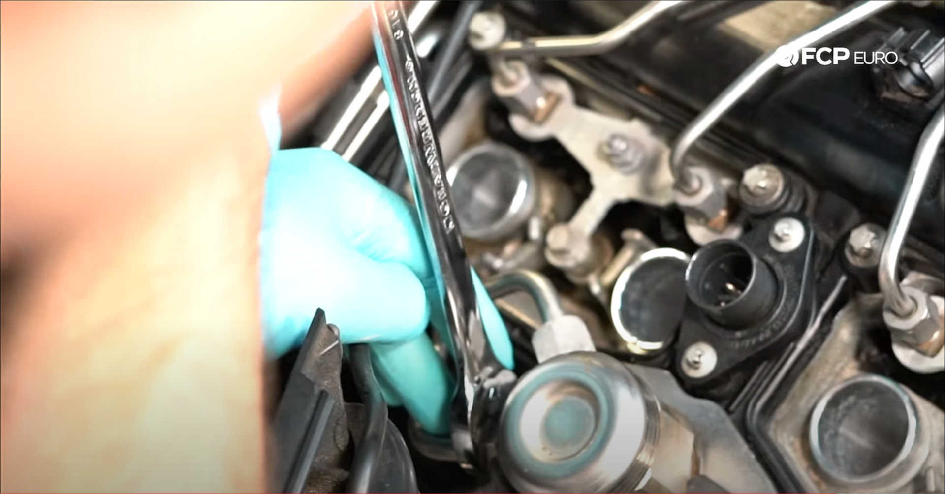
Step 17: Install the backside wiring harness
Move the harness over towards the back of the engine and the mounting bracket into position. The thickest part of the bracket will go towards the passenger's side of the engine. Use an E6 socket to tighten the three screws that mount the bracket to the valve cover and torque them to 6 N m. The third screw mounts to the back of the cover in a similar orientation to the vacuum pump bolts.
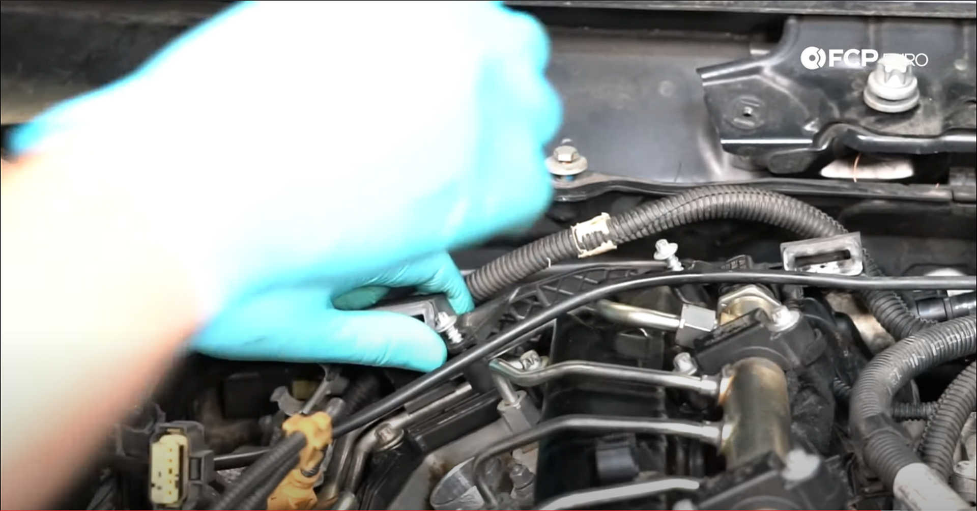
Move the remaining hose from the vacuum pump under the harness and around the engine. Then clip the harness onto the bracket behind the engine.
Plug in the O2 sensors. One of the plugs will have only four pins while the other has five. Clip them into the metal brackets once they're connected.
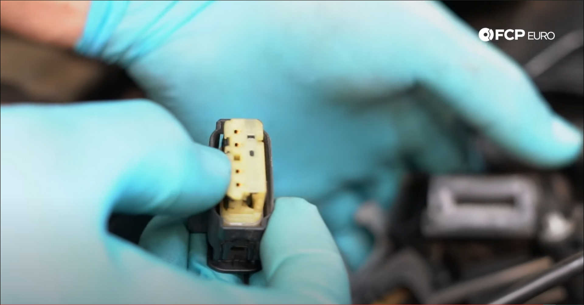
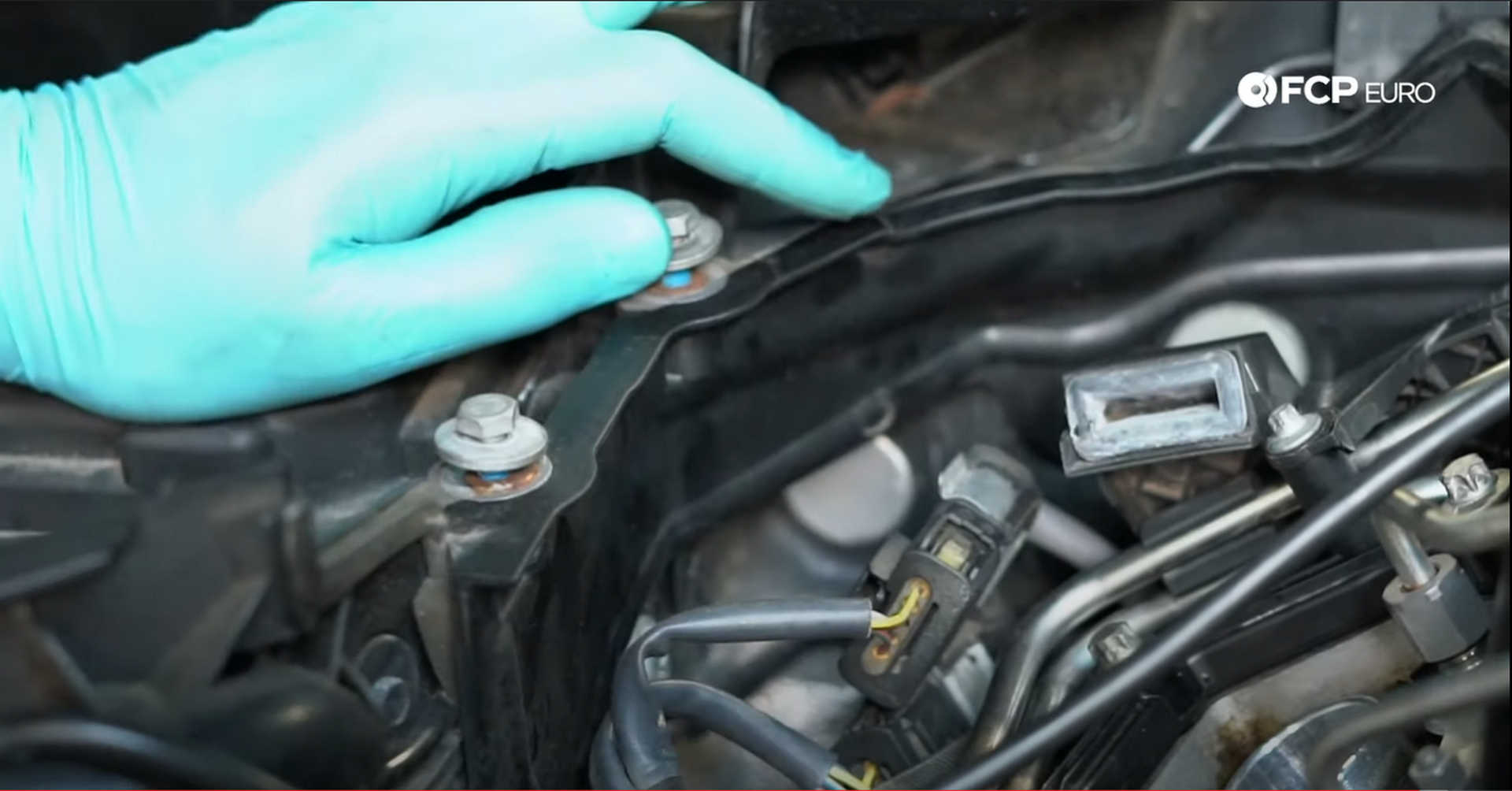
Next, plug in the high-pressure fuel pump and the boost control solenoid. After that, pull the Valvetronic plug over the valve cover, seat the harness in its clip, and plug it in.
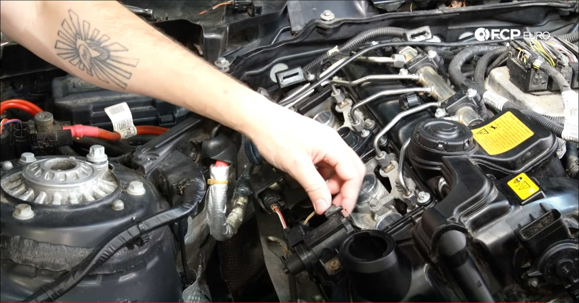
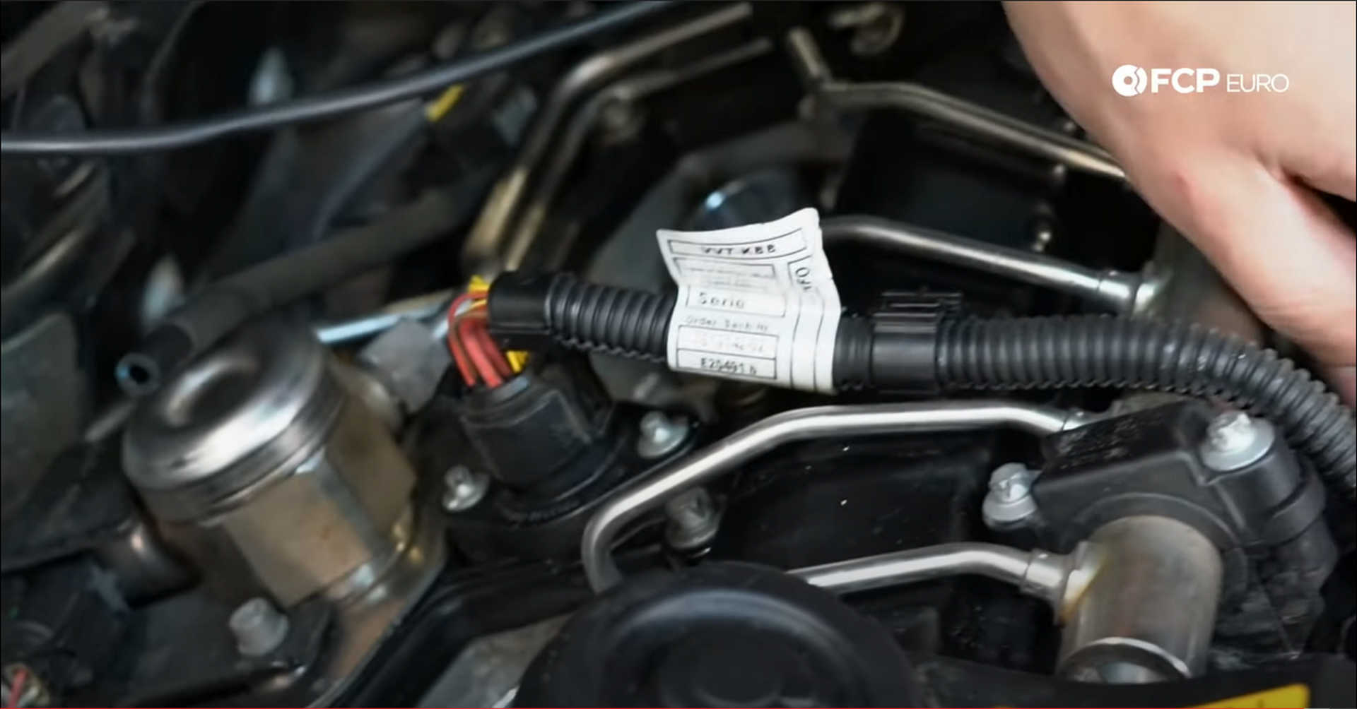
Step 18: Refit the ignition and fuel injector harness
This harness will swing around the front of the engine, with its bracket clipping onto the valve cover on either side of the high-pressure fuel pump. There is a small circular plug on the harness for the fuel pump and boost control solenoid. It will plug into the bracket on the ignition harness, and the ignition harness will run under the boost line going from the wastegate actuator to the boost solenoid.
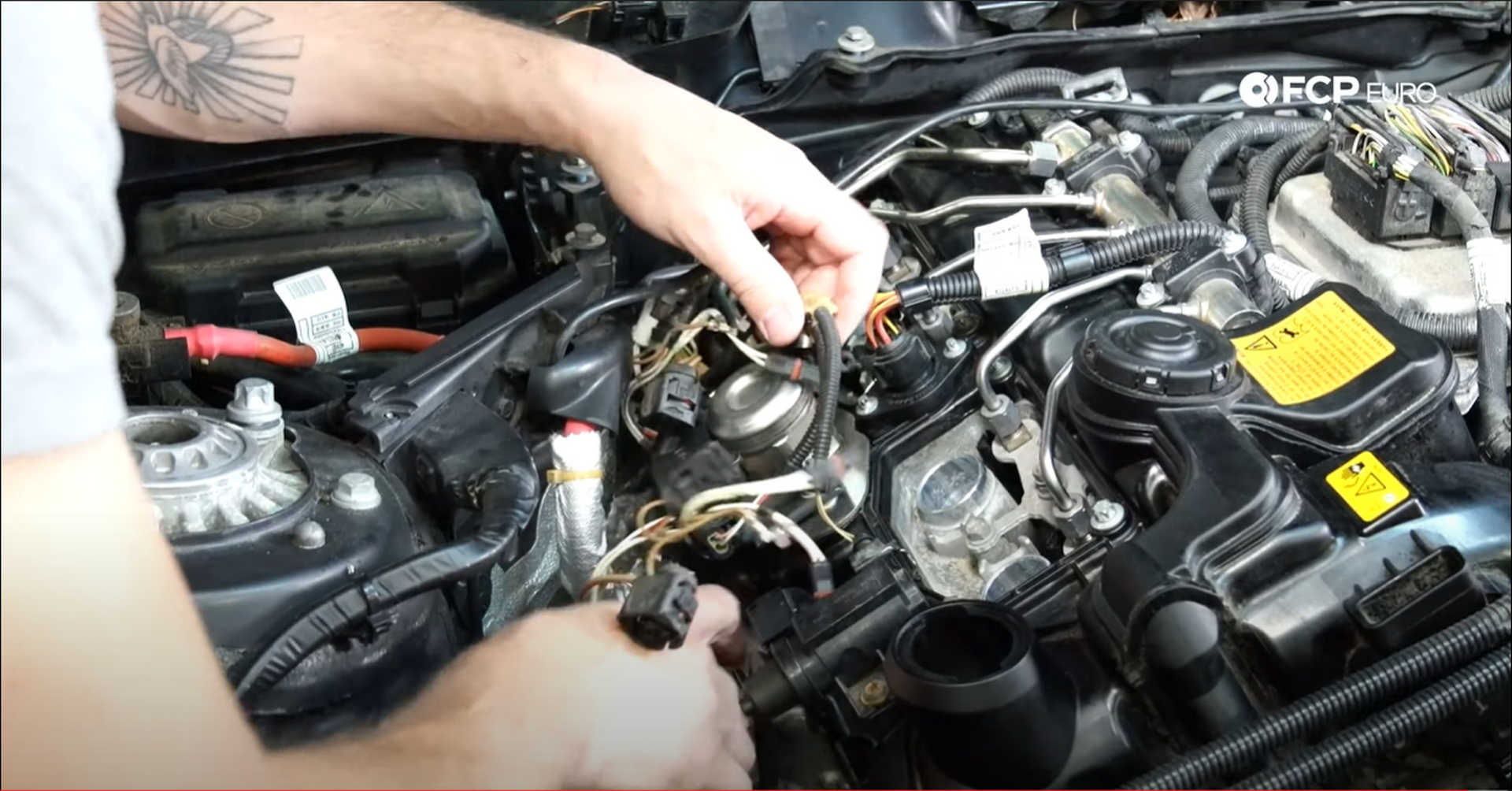
First, secure the two ground wires in between the injectors with their 8mm bolts. Then, before connecting anything else, fill the engine with oil, and change the filter. Tighten the oil filter cap to 25 N m when reinstalling it.
With the engine filled with oil, refit the negative cable onto the battery, but don't tighten it down. Grab your keys, head into the car, and turn the engine over with the starter to build oil pressure in the engine. To do that, do what you would do to normally start the car. Let the starter run for somewhere between 5 and 10 seconds, and repeat the process once more. Pull the negative cable off of the battery afterward.
Next, install the spark plugs and tighten them to 23 N m. Then, insert the ignition coils over the plugs and press them down to seat them. Flip-up the lock on the plug, and connect the harness to the coil, then lock them once connected. Lastly, plug the small two-pin connectors into the fuel injectors.
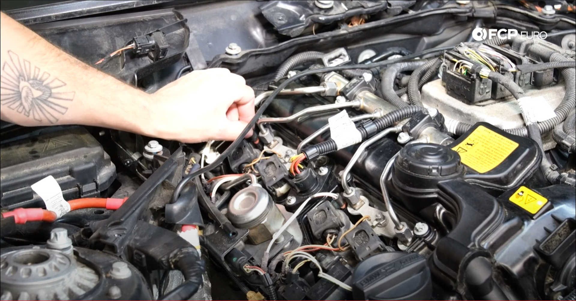
Go back to the battery, refit the negative cable onto the battery, and tighten it down once everything is connected.
At this point, you can start the car. If everything was done correctly, the car will start and run with no issues.
Step 19: Refit the underbody panels
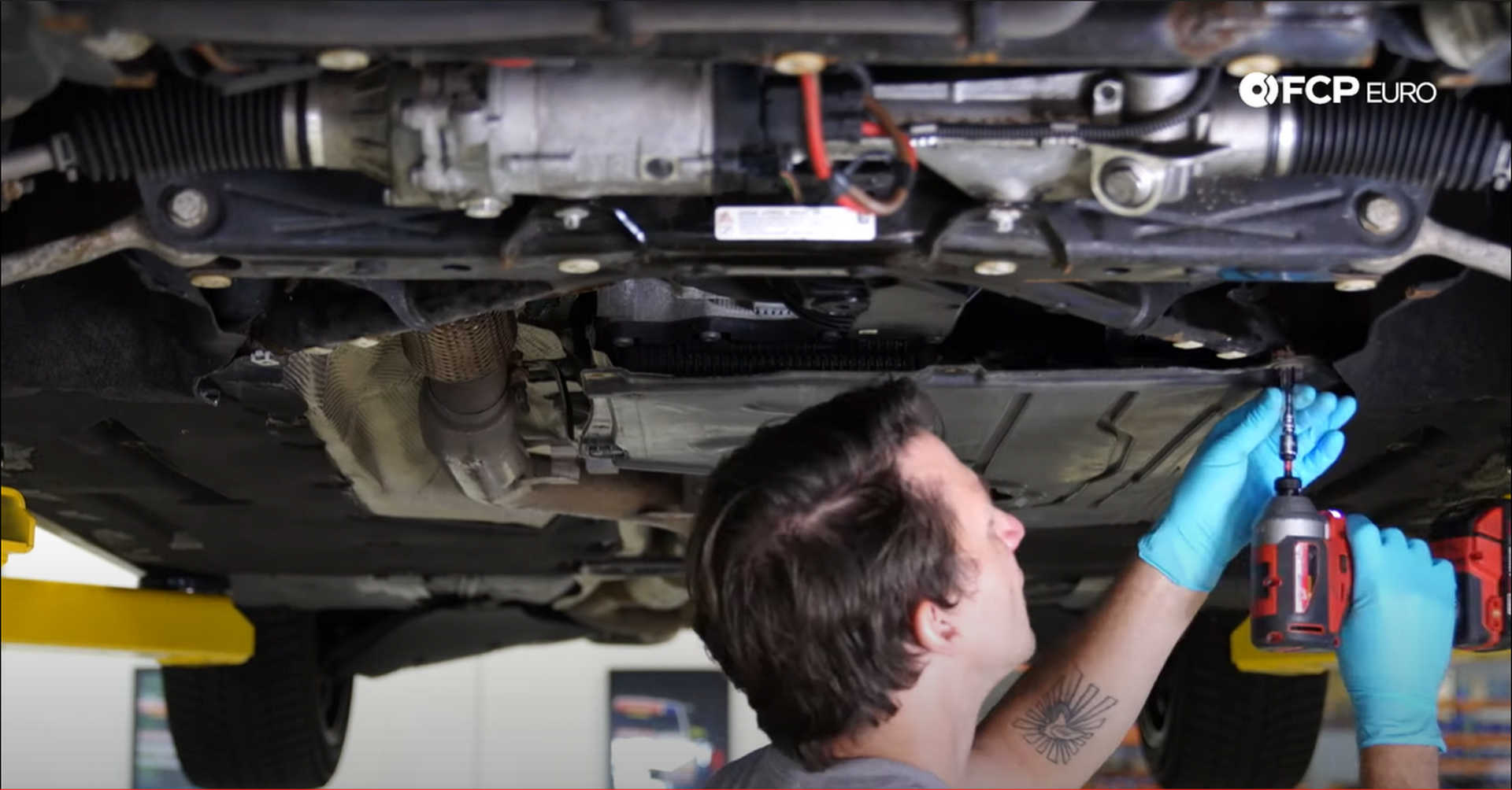
Fit the transmission cover onto the locating pin and slide it forward. Then, use an 8mm socket to tighten the six bolts mounting the panel to the car.
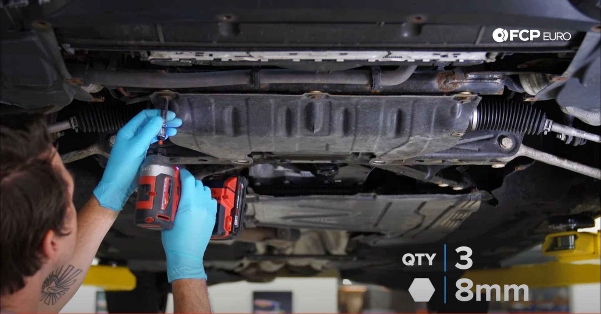
Next is the steering rack cover. Use an 8mm socket to secure the three 8mm fasteners at the front of the cover.
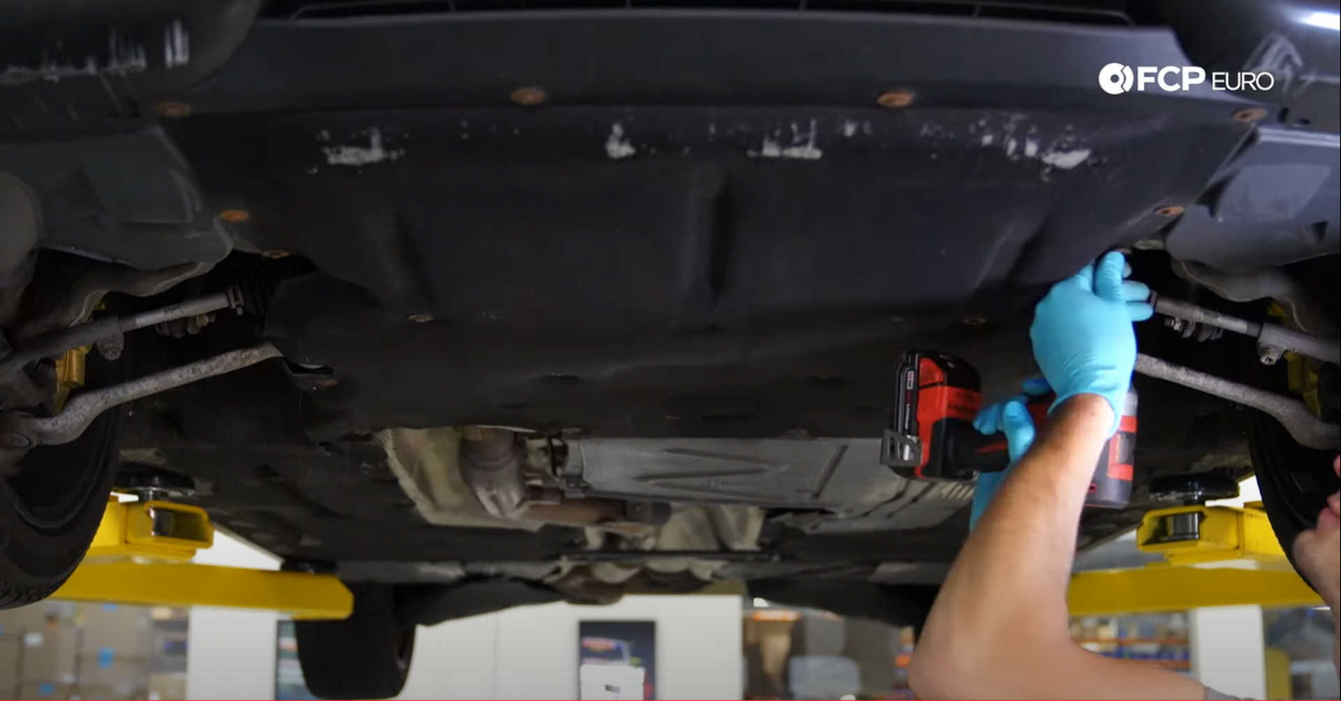
Lastly, mount up the belly pan to the car. Slide the front of the pan under the bumper and thread in one of the fasteners. Next, move to the back of the cover and thread in a fastener there. Then, thread in the rest of the fasteners before tightening all twenty of them down with an 8mm socket.
Step 20: Reinstall the airbox
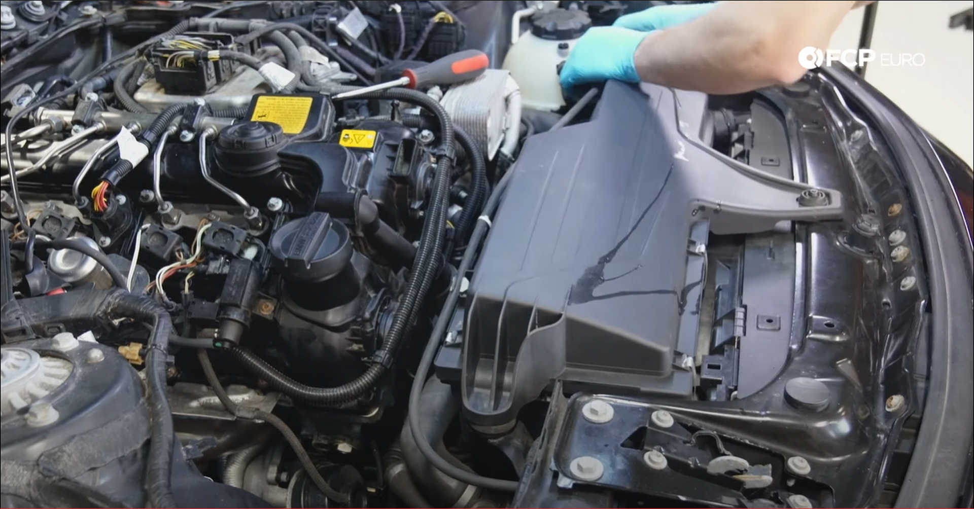
First, fit the airbox onto its rubber mounts. Then connect the intake pipe to the airbox and plug in the mass airflow sensor. Tighten down the intake pipe clamp with a flat-head screwdriver and fit the hood cable into the clips on the back of the airbox.
Step 21: Reinstall the cowl brace and trim
Take the brace and cowl cover, and set them onto their mounting points. Use a 10mm socket to secure the six bolts for the cowl cover to the car and an E20 socket to secure the four bolts that mount the brace to the car.
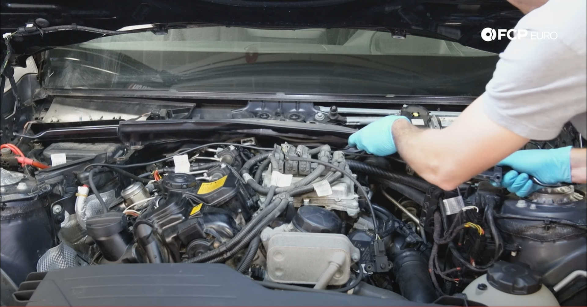
Next, sit the wiper cowl over the wiper motor and seat all of the locks into place. On either end, there are two push clips that lock it into place. Take a 5mm hex wrench and twist the locks in the center of the cowl 90° to the right to lock them, and the panel, down.
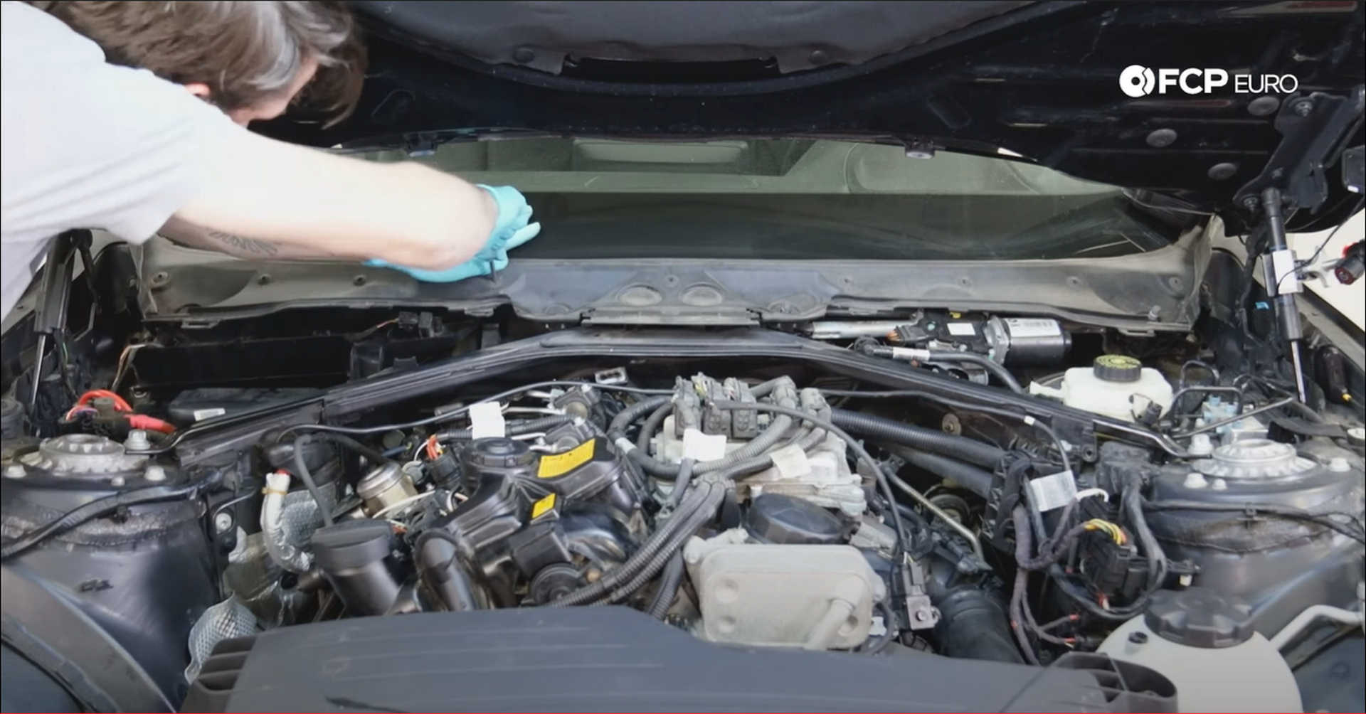
Place the wiper arms on the studs and tighten down the nuts with a 16mm socket. Place the rubber covers on the nuts once they're tight.
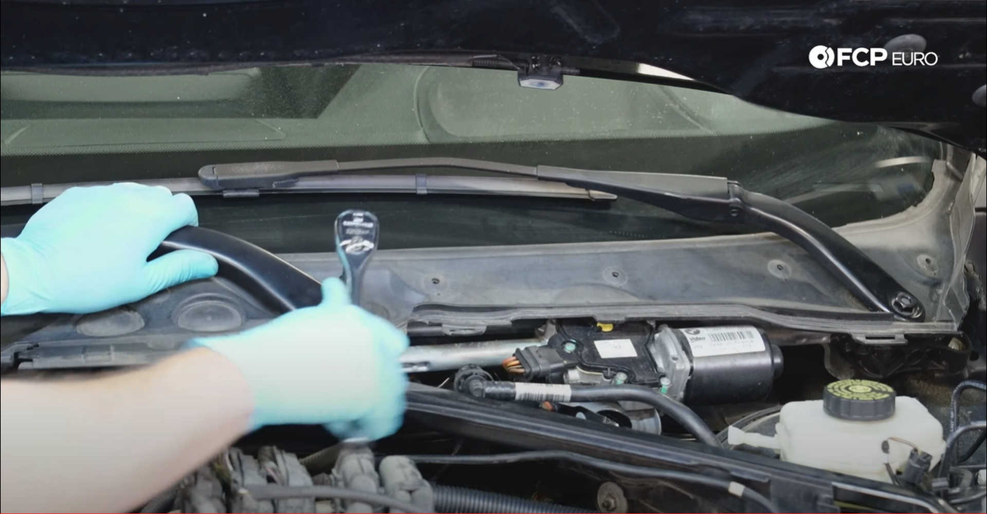
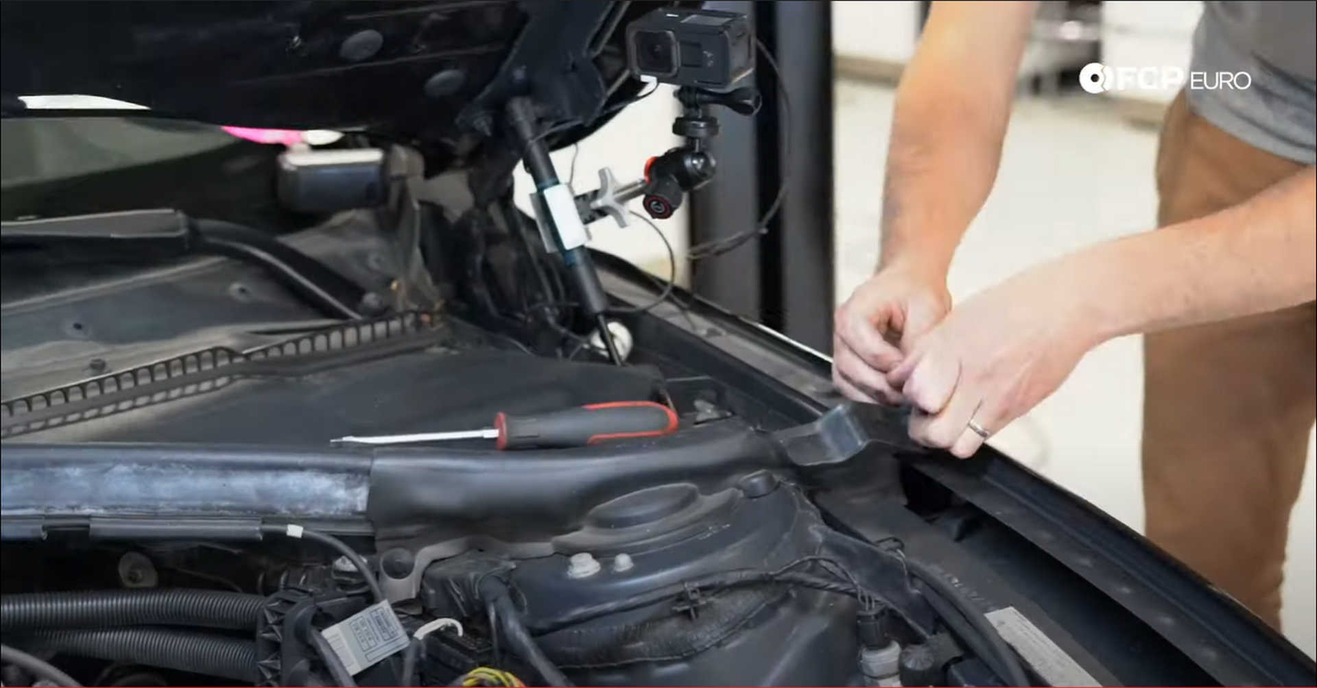
Next, refit the two-piece lower cowl. Each piece will slot into the middle cowl piece first, and then three plastic locks can be twisted into place with a 10mm socket. The forward-most corner will also fit into a rubber mounting grommet. Then place the rubber hood seal onto the brace with the rounded edge facing upward and run the cable through the lips on the front.
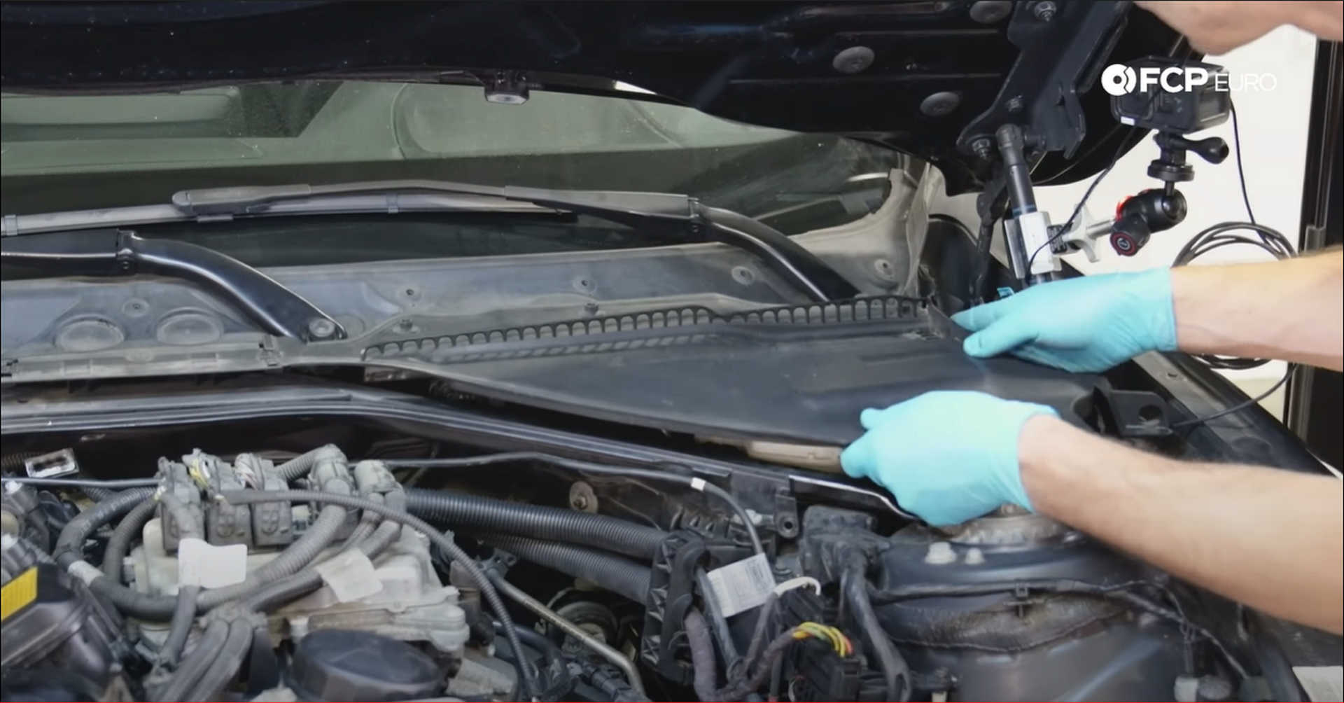
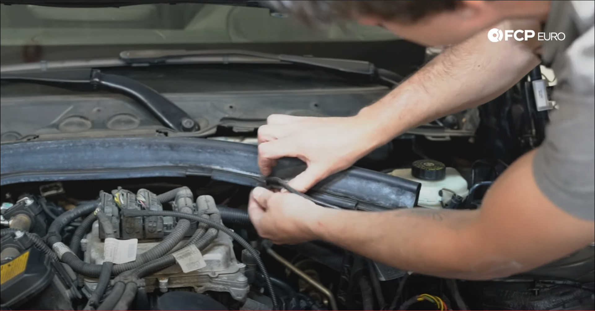
Lastly, install the strut top covers. The passenger's side cover will have one push clip near the fender and will clip onto the strut bolts. The driver's side cover will have one extra push clip, just on the inside of the strut tower.
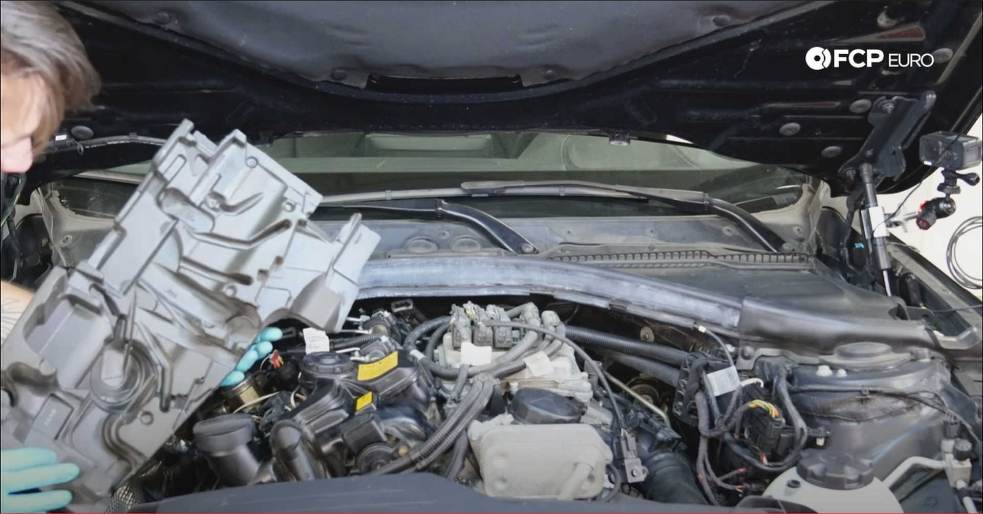
Step 22: Install the engine foam and cover
The sound deadening foam sits atop the engine, and under the plastic cover matches the top of the engine, which means that when it is sitting in the right spot, it should be relatively flat. The two slots at the back of the engine and the small mounting ball opposite the oil filler cap should be accessible for the plastic engine cover.
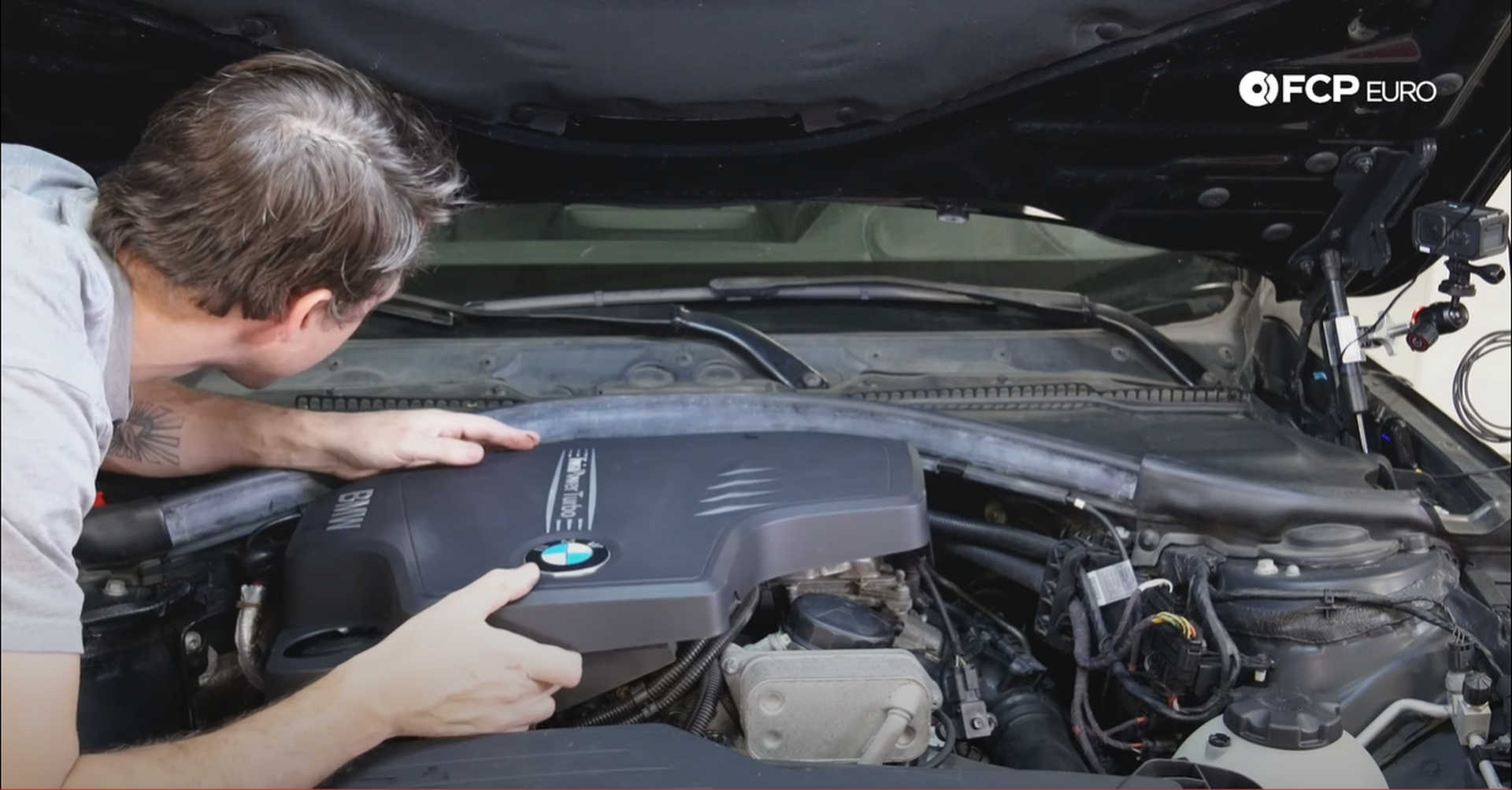
Slide the engine cover over the foam and into the two slots at the back of the engine. Then, press down on the front of the cover, locking it into place.
BMW N20 Timing Chain Replacement Torque Specs:
- BMW Oil Pump Drive Mounting Bolts = 10 N m or 7.4 lb-ft of torque
- BMW Oil Pump Sprocket Bolt = 95 N m or 70 lb-ft of torque
- BMW Timing Chain Guide Bolts = 10 N m or 7.4 lb-ft of torque
- BMW Timing Chain Upper Guide Pin = 14 N m or 10.3 lb-ft of torque
- BMW Timing Chain Lower Guide Pin = 24 N m or 17.7 lb-ft of torque
- BMW Camshaft Adjusters = 55 N m or 40.6 lb-ft of torque, plus 55°
- BMW Crankshaft Bolt = 100 N m or 74 lb-ft of torque, plus 270°
- BMW Upper Guide Pin Plug = 25 N m or 18.4 lb-ft of torque
- BMW Lower Guide Pin Plugs = 50 N m or 37 lb-ft of torque
- BMW Vibration Dampener Bolts = 35 N m or 25.8 lb-ft of torque
- BMW Camshaft Position Sensor Bolts = 6 N m or 4.4 lb-ft of torque
- BMW Oil Pickup Bolt = 10 N m or 7.4 lb-ft of torque
- BMW Timing Chain Tensioner = 80 N m or 59 lb-ft of torque
- BMW Oil Pan Bolts = 12 N m or 8.9 lb-ft of torque
- BMW Dust Shield Bolts = 10 N m or 7.4 lb-ft of torque
- BMW Valve Cover Bolts = 9 N m or 6.6 lb-ft of torque
- BMW Camshaft Adjustment Solenoids = 5.5 N m or 4 lb-ft of torque
- BMW Boost Control Solenoid = 5.5 N m or 4 lb-ft of torque
- BMW Vacuum Pump Bolts = 10 N m or 7.4 lb-ft of torque
- BMW Fuel Injector Connections = 23 N m or 17 lb-ft of torque
- BMW Fuel Rail Clamp Fasteners = 8 N m or 5.9 lb-ft of torque
- BMW High-Pressure Fuel Pump Bolts = 12 N m or 8.9 lb-ft of torque
- BMW High-Pressure Fuel Line Connections = 30 N m or 22.1 lb-ft of torque
- BMW Wiring Harness Bracket Screws = 6 N m or 4.4 lb-ft of torque
- BMW Oil Filter Housing Cap = 25 N m or 18.4 lb-ft of torque
- BMW Spark Plugs = 23 N m or 17 lb-ft of torque
We hope that you found this detailed guide on how to reinstall the timing chain system on your BMW N20 useful and save a large chunk of money in the process. If you're interested in more DIYs for your BMW, you can visit bmw.fcpeuro.com and subscribe to our YouTube channel.

