- 03/04/2021
- 6 Min Read
- By: Gareth Foley
How To Install Camshafts On A BMW M50/S50 Or M52/S52 Engine

Camshaft installation on BMW M50/S50 and M52/S52 engines (and the M52TU/M54/M56) engines have people afraid due to the length of the camshaft and the possibility of snapping one during removal or installation. However, there's no reason to worry; I'll show you how to do this safely and without any special tools.
While I have the engine out on my E36 for maintenance and upgrades, I was fortunate enough to get a great deal on a set of S50 camshafts. Originally, I wasn't sure if I was going to replace the cams, but when the S50 cams came up for sale, I had to go for it. The single VANOS family of BMW engines (M50TU/S50 and M52/S52) are so close to each other in specs that the camshafts from the M-series engines are easily interchangeable into the non-M engines. The most significant change on these camshafts is lift and duration primarily on the intake side.
However, maybe you're not upgrading cams for more power. Maybe you have awful scoring on some stock camshafts or damaged cam trays. Maybe you are having a cylinder head machined, and you want to strip it down for the machine shop. Well, the procedure outlined below is going to be the same regardless of whether you're installing upgraded camshafts or not.
The biggest thing I see on the internet regarding camshaft installation in these engines is the possibility of breaking a camshaft during installation or removal due to their length. I suppose it's a risk if you have an uneven load on the camshaft in the wrong spots, but that's highly unlikely. There are several methods out there, but my preference (and in my opinion the easiest) for removal is the two cam bearing cap method. This puts the evenest load distribution on the cam and has the least risk of the cam walking on you. Also, this method doesn't require any special tools.
Tools needed to install camshafts on a BMW M50, M52, S50 or S52:
- 8mm socket
- 10mm socket
- 10mm socket with deep broaching
- 11mm socket
- 13mm socket
- 19mm socket
- 22mm socket
- 32mm socket
- E8 Torx socket
- E10 Torx socket
- 24mm wrench
- 14mm spark plug socket
- Long ratchet
- Short ratchet
- Torque wrench
- Cam lock set
- VANOS wrench
Parts needed to complete to install camshafts on a BMW M50, M52, S50, or S52:
- Valve cover gasket
- Valve cover grommets
- VANOS line crush washers
- VANOS gasket
- Assembly lubricant
- RTV
- Lifters (optional)
- Cam trays (optional)
- Upper timing chain tensioner (optional)
- Upper timing chain guide (optional)
Step 1: Remove Ignition Coils, Valve Cover, Spark Plugs, and Anything Blocking Access to Front Crank Bolt
The ignition coils are held on with 10mm bolts. Remove the bolts, disconnect the electrical connector from the ignition coiling wiring harness, and remove the ignition coils. Next, use a 10mm socket to remove the valve cover cap nuts. There will be some grounds for the ignition coils on the inner cap nuts, and those can be removed with an 8mm socket. After all the cap nuts are removed, the valve cover can be removed and placed to the side. At this point, remove all items blocking access to the front crankshaft bolt. You will need access to the bolt to move the engine to top dead center and line up the timing marks on the crankshaft pulley and timing cover. Also, remove spark plugs to aid in barring the engine over.
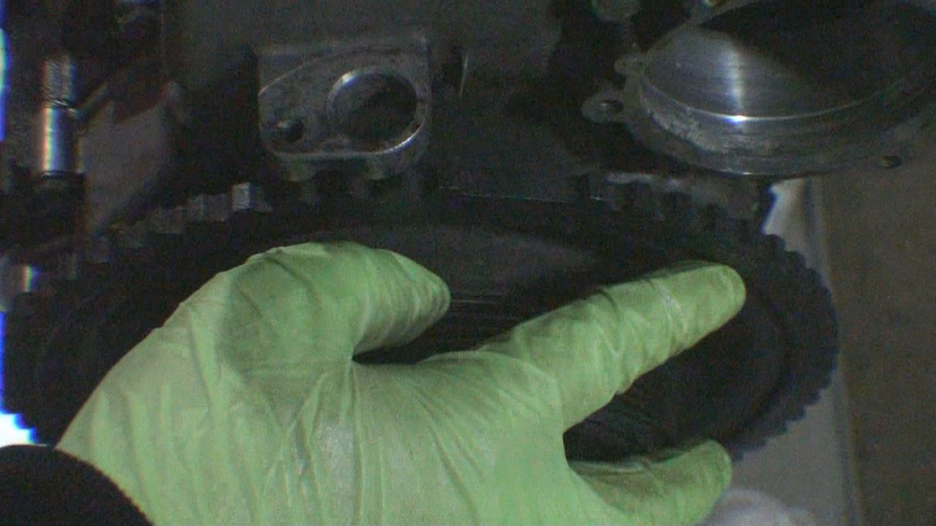
Step 2: Bring Engine to TDC and Lock Cams
Using a 22mm socket and long ratchet, rotate the engine clockwise until the timing marks on the crankshaft pulley and timing cover line up. Verify that the dots on the rear of the camshafts are pointing up, and the cam lobes for cylinder one are pointing at each other. At this point remove the stud bolts on the rear of the engine to insert the cam locks. The cam locks should drop into place; if they don't drop right in you can use a 24mm wrench to wiggle each cam until they do.
Step 3: Remove the VANOS Unit
First, remove the 19mm access caps on the front of the VANOS unit. This will give you access to the lower E10 bolts located on the exhaust cam upper chain sprocket. With the cam locks installed, break the E10 bolts loose on the exhaust cam but do not remove them. Using a lock pin, push down the secondary chain tensioner and lock it into the un-tensioned position. There shouldn't be any tension on the upper timing chain at this point.
Next, remove the 10mm and 13mm nuts securing the VANOS unit to the cylinder head. Also, remove the VANOS oil feed line banjo fitting with a 19mm wrench. You can disconnect the VANOS solenoid connector as well. Now, use your VANOS wrench to rotate the exhaust cam sprocket clockwise while pulling the VANOS unit off. Once the VANOS pops free from the cylinder head, you can pull it off.
Step 4: Remove Camshaft Sprockets and Associated Parts
Remove the E10 bolts from the exhaust sprocket and remove the 10mm nuts on the intake cam. Now, remove the 4mm plate, diaphragm spring, and 2mm plate from the intake cam. With all of the hardware removed, pull the upper timing chain and sprockets off the camshafts. With the upper timing chain removed, you can now remove the thrust washer stud bolts from the intake cam, as well as the reluctor ring for the cam sensor. You will need a deep 10mm socket with deep broaching to remove these stud bolts. Alternatively, you can use an open-ended wrench, but my recommendation is a 10mm deep socket.
You can now remove the upper timing chain tensioner (held in with four 10mm bolts) as well as the upper timing chain guide (held in with two E8 Torx bolts). Be sure you keep this hardware together in the proper orientation. Next, remove the primary timing chain tensioner with a deep 32mm socket or wrench. You can now remove the primary camshaft sprocket and chain from the exhaust cam. Make sure you don't let the timing chain fall into the timing case. I hung it off the side of the cylinder head with safety wire and a large socket.
Step 5: Move Crankshaft 45 Degrees Clockwise Off TDC (If Cylinder Head is Still Installed on the Engine)
With the camshafts still locked in TDC, move the crankshaft 45 degrees clockwise. The reason for this is to allow room for the valves to open fully while rotating the cam into proper position for removal. I have the spark plugs pulled for this and use long, equal-length, quarter inch extensions to visually confirm the position of the pistons relative to TDC. Once you're 45 degrees off TDC, you can remove the cam locks.
Step 6: Rotate the Camshafts to Confirm Clearance
With the crankshaft 45 degrees off TDC, you should be able to fully rotate each camshaft a full 360 degrees with no resistance. If you feel resistance, check the crank position and rotate further past TDC in the clockwise position. However, as long as you're close to 45 degrees, all of the pistons should be down far enough to not interfere with the valves.
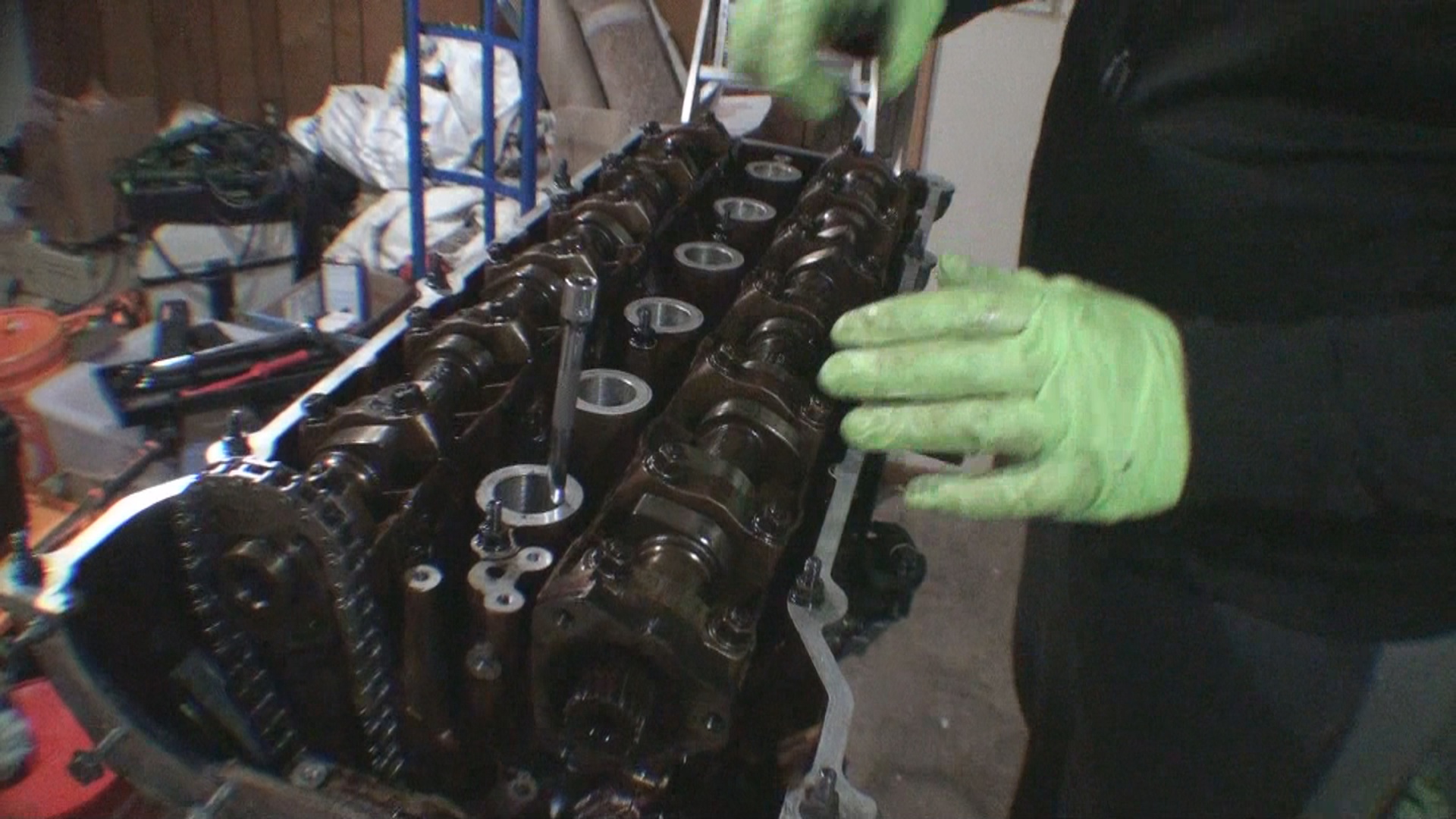
Step 7: Ready Camshaft for Removal
First, take note of the cap numbers on the camshaft bearing ledge. For the intake cam they're labeled E1-E7, and on the exhaust side, they are labeled A1-A7. The numbering is done from the front to the rear of the engine sequentially. Take note of the position in which way the caps are installed as they will need to be installed in the same direction. The lettering on both the intake and exhaust cam bearing ledge caps should be positioned inwards towards the spark plug tubes. Now that you have confirmed there isn't valve to piston interference, you're ready to move the cam into position for removal.
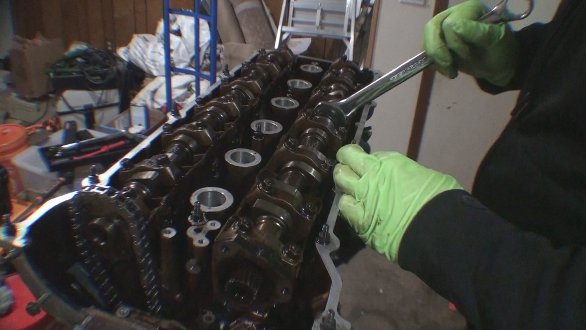
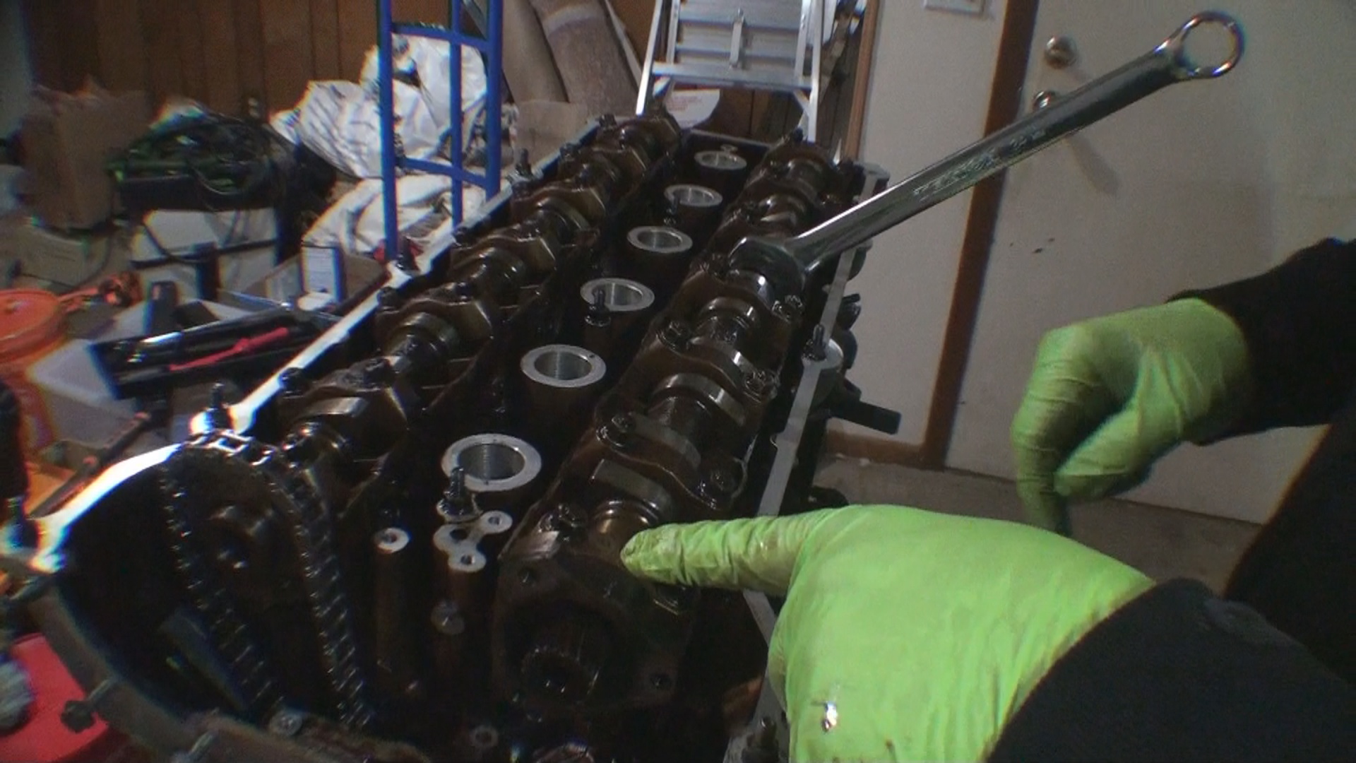
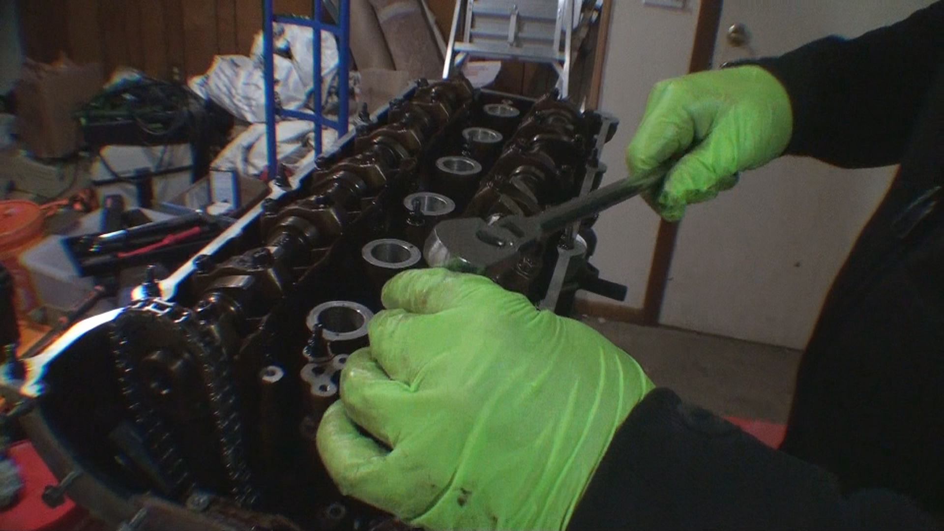
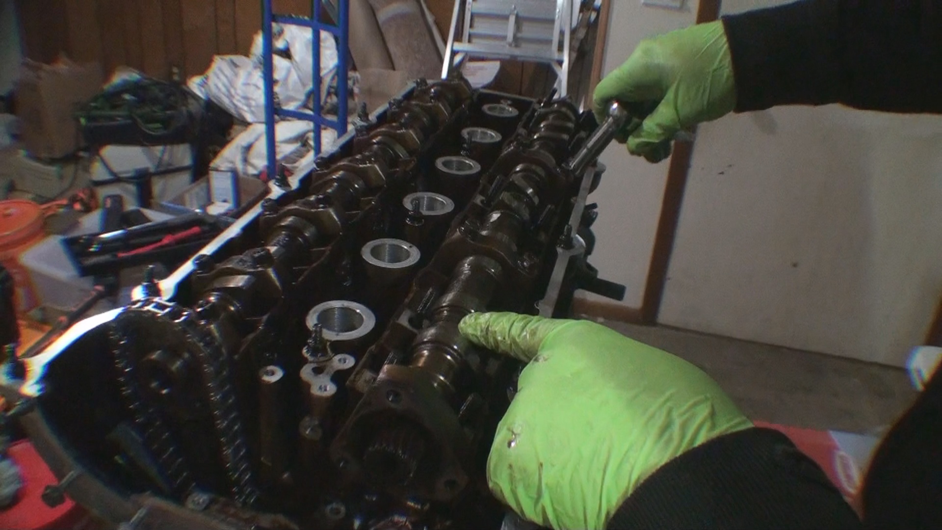
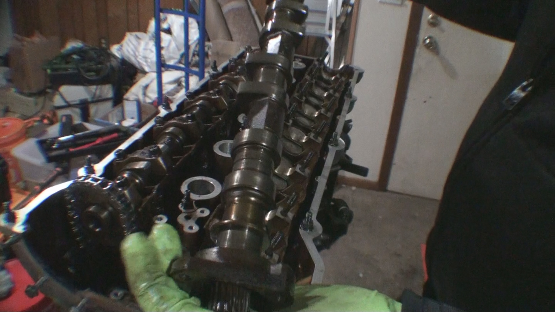
Step 8: Remove Camshaft
Like I mentioned earlier, we will be removing the cams with the two cap method. To do this, you must rotate the cam you are removing first so that the lobes are coming off cylinder 2 and the lobes just going on to cylinder 4. Neither lobe should be depressing a lifter. From this position, you can now remove the 11mm nuts on the caps numbered 1, 3, 4, 6, and 7. You will leave the nuts on 2 and 5 tight. Remove the caps in which the nuts have been removed and put those off to the side. Now you will loosen the nuts on 2 and 5 a quarter turn at a time, alternating on each nut until the nuts have been completely removed. At this point, remove cap 2 and 5. The camshaft can now be removed from the cam bearing ledge. If the cam is stuck in place, try to rotate it by hand, and it should lift off the tray. You can proceed to remove the cam tray and lifters (if you need to do so) keeping track of where each lifter sits. This is critical because each lifter wears uniquely with each valve, so it's important to match them back up to their corresponding valve.
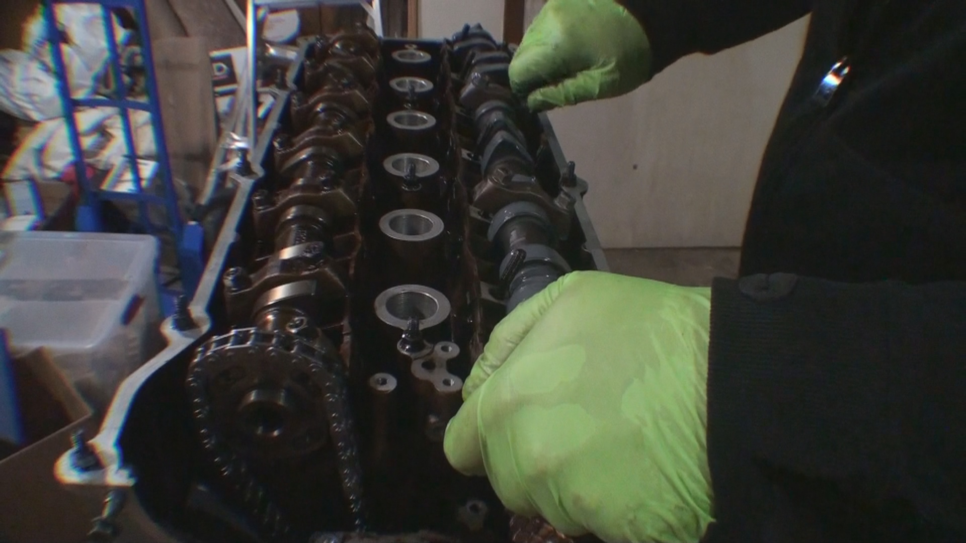
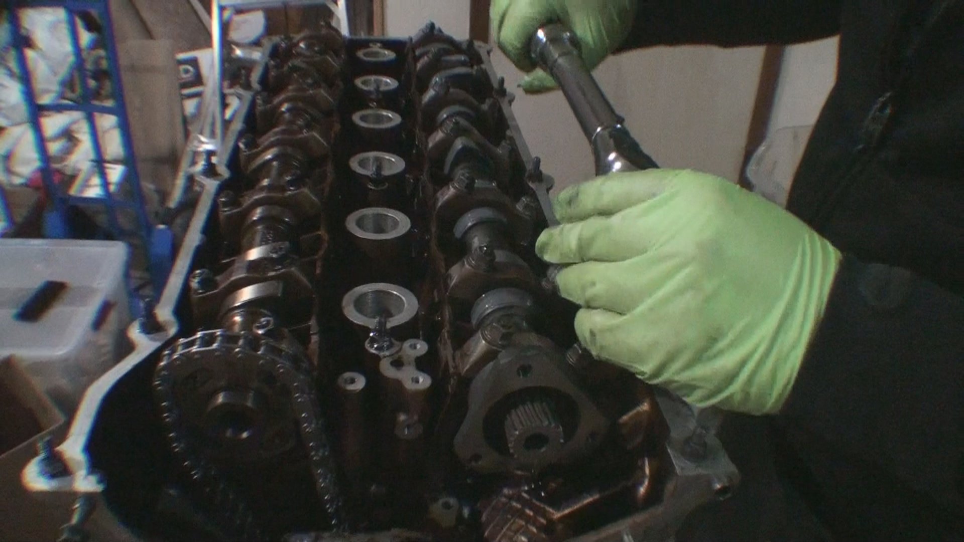
Step 9: Install Camshaft
Assuming the cam trays and lifters are back into position if they have been removed, you'll want to do some prep before installing the cams. You want to apply assembly lubricant to the lifters, cam bearing ledge journals, cam bearing ledge caps, and the cams themselves.
I used LIQUI MOLY LM48 assembly lube for my installation. This is essentially an MoS2 paste which has excellent lubrication properties for initial startup.
Once everything is lubricated and ready for installation, place the camshaft back into the cam bearing ledge. You will want to position it so that the lobes are in the same position they were for removal. Now, install cam bearing ledge caps #2 and #5. Thread the 11mm nuts on by hand so that the threads are engaged and there is some pressure on the cam. If one of the studs isn't exposed far enough to thread on the nut, you can rotate the cam by hand, and the cap will basically fall down into place. Turn each 11mm nut by hand a quarter turn, alternating on each cap until they're bottomed out. Now, you can install caps #1, #3, #4, #6, and #7. You can fully thread the nuts for the other caps down right immediately as there isn't any load on these caps or the cam journals. Torque the 11mm nuts to 14Nm, starting with cap #4 and working your way out, alternating from #3 to #5, and then from #2 to #6 and so on. After you've done this, rotate the camshaft back to TDC.
Step 10: Reinstall Timing Components and Re-Time Engine
Before installing any timing components, make sure the camshafts are locked in top dead center and then move the crankshaft counterclockwise back to top dead center. This article here explains the timing procedure for single VANOS engines that you can reference as well as info on the installation of the VANOS unit.
Torque Specs:
- Camshaft bearing ledge cap torque spec - 11mm hex - 14Nm
- Upper timing chain guide - E8 Torx - 10Nm
- Upper timing chain tensioner - 10mm hex - 10Nm
- Intake cam stud bolts - 10mm hex - 20Nm
- Intake cam stud bolt nuts - 10mm hex - 10Nm
- Timing chain tensioner - 32mm hex - 70Nm
- Exhaust cam sprocket bolts - E10 Torx - 15Nm
- VANOS plugs - 19mm hex - 50Nm
- VANOS banjo bolt - 19mm hex - 32Nm
- VANOS mounting nuts - 10mm hex - 10Nm
- Valve cover cap nuts - 10mm hex - 10Nm
Final Thoughts:
As you can see, you can do this job without any special tools. Interestingly enough, the special tool from BMW essentially mimics what the two cam bearing ledge cap method achieves. What you are looking to do is keep evenly distributed pressed on the camshaft as much as possible for safe removal and installation. Another thing that makes this technique even more useful is the fact that it's a one person job and there's no risk of the cam walking on you as neither the lobes on cylinder 2 or cylinder 4 are fully depressing the lifters.
You can follow the rest of my project by checking back here, subscribing to FCP Euro's YouTube channel, my personal YouTube channel, and my Instagram. And, if you have any questions or comments, leave them in the comments below.